Supporting foot hoop device for power pole tower

A technology of supporting foot hoop and power pole tower, applied in the direction of tower, building type, building, etc., can solve the problems of low support strength, inconvenient installation, inconvenient use, etc., and achieve the effect of high support strength, convenient installation and convenient use.

Active Publication Date: 2020-08-28
国网河南省电力公司鄢陵县供电公司
View PDF18 Cites 1 Cited by
  • Summary
  • Abstract
  • Description
  • Claims
  • Application Information

AI Technical Summary

Problems solved by technology

[0003] Existing foot support hoops such as Figure 8 and Figure 9 As shown, it includes half ring hoop C101, half ring hoop D102, foot rod 103 and earring fastening part 104. The two earring fastening parts 104 symmetrically arranged on both sides surround and fasten the half-ring hoop C101 and the half-ring hoop D102 and install them on the power pole tower. At the same time, the two support rods 103 arranged symmetrically on both sides can be positioned above it The cross-arm provides support; but there are problems of inconvenient installation, inconvenient use, and low support strength

Method used


Image

  • Supporting foot hoop device for power pole tower
  • Supporting foot hoop device for power pole tower
  • Supporting foot hoop device for power pole tower

Examples


Embodiment Construction

[0023] The technical solutions of the present invention will be further specifically described below through embodiments and in conjunction with the accompanying drawings.

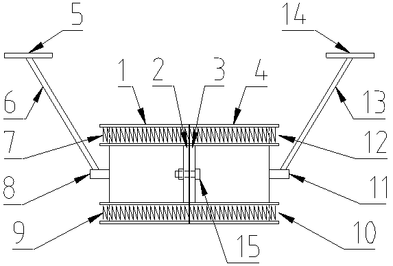
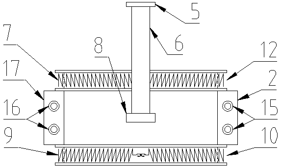
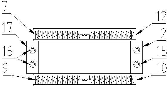
[0024] like figure 1 , figure 2 , image 3 , Figure 4 and Figure 5 As shown, the present invention provides a kind of support foot hoop device for power tower, including half-ring hoop A1 and half-ring hoop B4, which are enclosed together by half-ring hoop A1 and half-ring hoop B4, which can hold the power pole and tower tightly. The supporting feet are installed on the power pole tower, so that the supporting feet can provide support for the cross arm.

[0025] The upper and lower sides of the half-ring hoop A14 and half-ring hoop B are symmetrically provided with an annular groove A12 and an annular groove B10, and the annular groove A12 and the annular groove B10 are respectively provided with matching hook extension springs A7 and hook extension springs B9, hook extension springs A7 and hook t...


PUM


Abstract

The invention discloses a supporting foot hoop device for a power pole tower. The supporting foot hoop device comprises a semi-ring hoop A and a semi-ring hoop B, wherein a ring-shaped slot A and a ring-shaped slot B are symmetrically formed outside upper and lower parts of the semi-ring hoop A and the semi-ring hoop B; a hook tension spring A and a hook tension spring B are arranged in the ring-shaped slot A and the ring-shaped slot B; the end parts, between the ring-shaped slot A and the ring-shaped slot B, of the semi-ring hoop A and the semi-ring hoop B are separately and symmetrically provided with a lug plate A, a lug plate B, a lug plate C and a lug plate D; and centers, between the ring-shaped slot A and the ring-shaped slot B, of the semi-ring hoop A and the semi-ring hoop B are separately and symmetrically provided with a supporting foot A and a supporting foot B. According to the supporting foot hoop device disclosed by the invention, the ring-shaped slots and the hook tension springs are adopted to help pre-positioning during hoop mounting, so that follow-up mounting is convenient; flat supporting plates are adopted, so that the supporting foots are combined with a cross arm very well, and therefore, use is convenient; and connecting strength is improved through fixed blocks, fastening is assisted through the hook tension springs, and friction is increased through barbs, so that integral supporting strength of a supporting foot hoop is greatly improved.

Description

technical field [0001] The invention belongs to the technical field of electric power transmission auxiliary facilities, and in particular relates to a leg hoop device for a power pole and tower. Background technique [0002] The support hoop is used to provide support for the cross arm installed on the power pole tower, helping the cross arm to bear more weight to meet the needs of power development. [0003] Existing foot support hoops such as Figure 8 and Figure 9 As shown, it includes half ring hoop C101, half ring hoop D102, foot rod 103 and earring fastening part 104. The two earring fastening parts 104 symmetrically arranged on both sides surround and fasten the half-ring hoop C101 and the half-ring hoop D102 and install them on the power pole tower. At the same time, the two support rods 103 arranged symmetrically on both sides can be positioned above it The cross arm provides support; but there are problems of inconvenient installation, inconvenient use, and low...

Claims


Application Information

Patent Timeline
IPC IPC(8): E04H12/24
CPCE04H12/24
Inventor 马丽程浩王志伟庄立毕智勇田俊红马潇古佳明张誉文芦素芬孔琳琳
Owner 国网河南省电力公司鄢陵县供电公司
Why Eureka
Try Eureka