
Self-maintenance device for computerized embroidery device

A self-maintenance and equipment technology, used in embroidery machines, embroidery machine mechanisms, textiles and papermaking, etc., can solve problems such as damage to the needle drive mechanism, inability to lubricate, and inappropriate oil amount during oiling

Inactive Publication Date: 2020-09-01
海宁埃尔佳鞋业有限公司
View PDF0 Cites 0 Cited by
  • Summary
  • Abstract
  • Description
  • Claims
  • Application Information

AI Technical Summary

Problems solved by technology

[0003] The maintenance of existing embroidery machines is mostly to inject lubricating oil into the driving mechanism of the needle within a fixed period of time to ensure the smooth operation of the equipment, but the existing oiling equipment is fixed and cannot be lubricated according to the number of needle movements , so there will be a phenomenon that the oil filling time does not match the oil volume inside the needle drive mechanism, which will cause damage to the needle drive mechanism. Therefore, a self-maintenance device for computerized embroidery equipment has emerged as the times require.

Method used


Image

  • Self-maintenance device for computerized embroidery device
  • Self-maintenance device for computerized embroidery device
  • Self-maintenance device for computerized embroidery device

Examples


Embodiment Construction

[0025] The following will clearly and completely describe the technical solutions in the embodiments of the present invention with reference to the accompanying drawings in the embodiments of the present invention. Obviously, the described embodiments are only some, not all, embodiments of the present invention. Based on the embodiments of the present invention, all other embodiments obtained by persons of ordinary skill in the art without making creative efforts belong to the protection scope of the present invention.

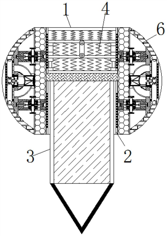
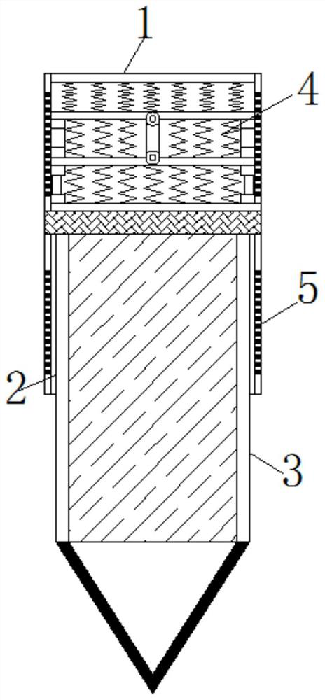
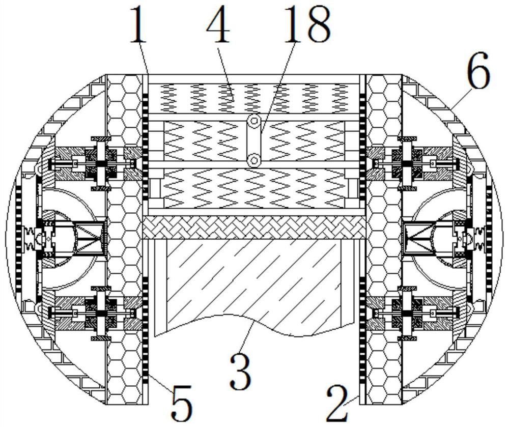
[0026] see Figure 1-8 , a self-maintenance device for computer embroidery equipment, comprising a housing 1, a chute 2 is opened inside the housing 1, a needle 3 is slidably connected to the surface of the chute 2, the lower end of the needle 3 is designed as a triangle, and the tip is facing downward , the needle 3 is made of metal; the top of the needle 3 is movably connected with a reciprocating spring 4, and the inside of the reciprocating spring 4 is mov...


PUM


Abstract

The invention relates to the technical field of computerized embroidery machine maintenance, and discloses a self-maintenance device for a computerized embroidery device. The self-maintenance device for the computerized embroidery device comprises a shell, a sliding chute is formed in the shell, a surface of the sliding chute is in sliding connection with a needle head, a top part of the needle head is movably connected with a reciprocating spring, two sides of the sliding chute both are fixedly connected with oil discharge plates; one side of each oil discharge plate, far away from the sliding chute, is fixedly connected with a maintenance box; the surface of a screw is movably connected with a gas storage bag; one side of the gas storage bag, far away from the screw, is movably connectedwith a spring plate; an engagement rod is movably connected in the screw; one end of the engagement rod, far away from the screw, is movably connected with a push rod, a surface of the push rod is movably connected with a torsion spring, and one end of the push rod, far away from the engagement rod, is fixedly connected with a piston block; and the surface of the piston block is movably connectedwith an oil storage bag. The oil storage bag squeezes out oil stored therein from the oil discharge plate located at an upper part of the shell when being pressed, and consequently, an effect of automatic-control oil injection maintenance according to times of movement of the needle head is realized.

Description

technical field [0001] The invention relates to the technical field of computer embroidery machine maintenance, in particular to a self-maintenance device for computer embroidery equipment. Background technique [0002] Computerized embroidery machine refers to the process of preparing patterns by punching out cards, tapes or discs or through digital processing, guiding or stimulating embroidery machines and embroidery frames for various movements required for design; existing computerized embroidery machines use computer programming Setting the moving trajectory of the needle to complete the pattern embroidery has the characteristics of fast accuracy and diversified embroidery methods, while the embroidery machine is a mechanical device that requires daily maintenance. [0003] The maintenance of existing embroidery machines is mostly to inject lubricating oil into the driving mechanism of the needle within a fixed period of time to ensure the smooth operation of the equipm...

Claims


Application Information

Patent Timeline
Patent Type & Authority Applications(China)
IPC IPC(8): D05C13/04D05C13/00D05C11/02
CPCD05C11/02D05C13/00D05C13/04
Inventor 沈雨文
Owner 海宁埃尔佳鞋业有限公司
Learn More