
Timed throwing bomb

A technology of elastic parts and end caps, which is applied in the field of throwing bombs, can solve the problems of inaccurate timing, difficulty in accurately attacking lawbreakers, and lack of preventive weapons, etc., to achieve the effect of precise timing and accurate strikes

Inactive Publication Date: 2020-09-01
遂宁晶安科技有限公司
View PDF6 Cites 0 Cited by
  • Summary
  • Abstract
  • Description
  • Claims
  • Application Information

AI Technical Summary

Problems solved by technology

[0002] With the development of society, new social security problems continue to emerge. However, our country's police explosion-proof non-lethal weapons and equipment are far from meeting the needs of actual combat, and cannot implement sufficient defense in maintaining social stability and responding to emergencies. Sexual behavior, especially in the face of extraordinary moments such as mass riots, there is no proper defensive weapon, which has seriously restricted the combat effectiveness of public security officers for a long time
Among them, tear gas bombs and flash bombs are commonly used explosion-proof non-lethal weapons and equipment. Tear gas bombs include gas tear gas bombs, powder tear gas bombs and liquid tear gas bombs, etc., which are non-lethal ammunition. After detonation, tear gas, tear gas powder and tear gas liquid will be released. To disperse the crowd and prevent criminals from further destructive behavior, but most of the current tear gas bombs are fired with a primer. On the one hand, this structure cannot be accurately timed, and it is difficult to accurately strike criminals. On the other hand, there are certain safety hazards in transportation and storage. Affect

Method used


Image

  • Timed throwing bomb
  • Timed throwing bomb
  • Timed throwing bomb

Examples


Embodiment Construction

[0022] Embodiments of the present invention are described in detail below, examples of which are shown in the drawings, wherein the same or similar reference numerals designate the same or similar elements or elements having the same or similar functions throughout. The embodiments described below by referring to the figures are exemplary only for explaining the present invention and should not be construed as limiting the present invention.

[0023] In the description of the present invention, it should be understood that the orientation descriptions, such as up, down, front, back, left, right, etc. indicated orientations or positional relationships are based on the orientations or positional relationships shown in the drawings, and are only In order to facilitate the description of the present invention and simplify the description, it does not indicate or imply that the device or element referred to must have a specific orientation, be constructed and operated in a specific ...


PUM


Abstract

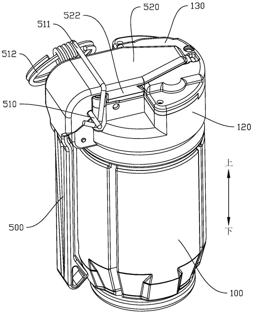
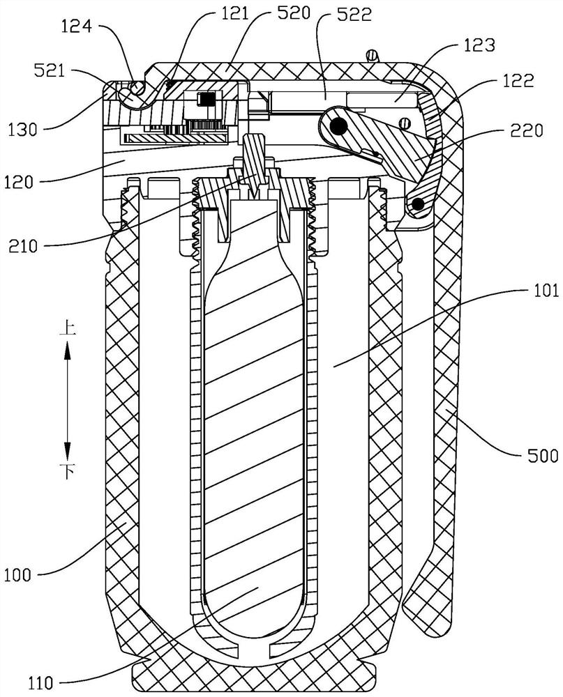
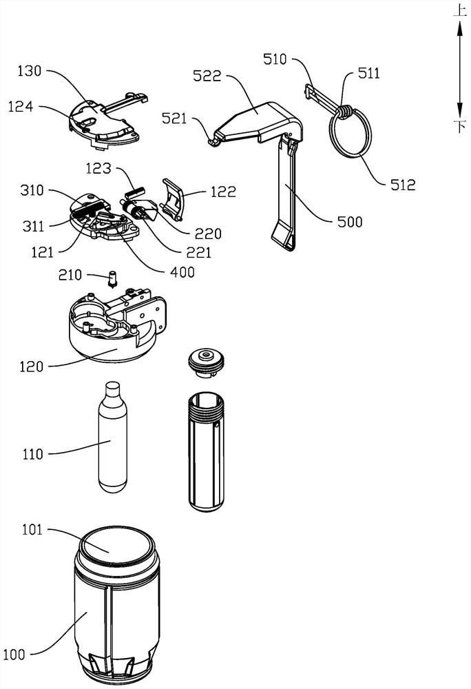
The invention discloses a timed throwing bomb which has the characteristics of precisely controlling the detonation time. The timed throwing bomb includes a tank body with an inner cavity, a gas storage tank arranged in the inner cavity, an end cover connected to the upper end of the tank body, a firing device connected to the end cover, a timing mechanism connected to the end cover and a handle connected to the end cover; the firing device includes a striker for piercing the gas storage tank and a rotary ram for firing the striker, and the rotary ram is connected with a pre-tensioned torsionspring; the timing mechanism includes a striker bar, a transmission gear, and a timing gear, the striker bar is connected with an elastic member, the striker bar is provided with a rack, the transmission gear is provided with a coaxial pinion, the pinion meshes with the rack, the transmission gear meshes with the timing gear, and the timing gear is connected with a buffer mechanism; the handle islocked on the end cover by a pin, the handle in a locked state limits the striker bar, and the end cover is connected with a spring for pushing the handle open; and the end cover is provided with a pressure plate for locking the rotary ram, and the striker bar moves under the push of the elastic member to push a pressure plate away.

Description

technical field [0001] The invention relates to the technical field of throwing bombs, in particular to a timing throwing bomb. Background technique [0002] With the development of society, new social security problems continue to emerge. However, our country's police explosion-proof non-lethal weapons and equipment are far from meeting the needs of actual combat, and cannot implement sufficient defense in maintaining social stability and responding to emergencies. Sexual behavior, especially in the face of extraordinary moments such as mass riots, there is no proper defensive weapon, which has seriously restricted the combat effectiveness of public security officers for a long time. Among them, tear gas bombs and flash bombs are commonly used explosion-proof non-lethal weapons and equipment. Tear gas bombs include gas tear gas bombs, powder tear gas bombs and liquid tear gas bombs, etc., which are non-lethal ammunition. After detonation, tear gas, tear gas powder and tear ...

Claims


Application Information

Patent Timeline
Patent Type & Authority Applications(China)
IPC IPC(8): F42B12/46F42B3/16
CPCF42B12/46F42B3/16
Inventor 林文胜
Owner 遂宁晶安科技有限公司
Learn More