Supercharge Your Innovation With Domain-Expert AI Agents!

A method and system for measuring pantograph wear based on 3D imaging

A measurement method and pantograph technology, applied in the direction of measuring devices, instruments, optical devices, etc., can solve the problem of difficulty in extracting fine three-dimensional information of pantographs, limited accuracy of wear calculation, and inability to realize rapid and automatic detection of pantograph wear, etc. problem, to achieve the effect of reducing matching error, improving discrimination accuracy, and improving image feature effect

Active Publication Date: 2021-11-09
CHENGDU TANGYUAN ELECTRICAL APPLIANCE
View PDF7 Cites 0 Cited by
  • Summary
  • Abstract
  • Description
  • Claims
  • Application Information

AI Technical Summary

Problems solved by technology

[0005] However, this detection scheme for pantographs still has the following defects: first judge whether the pantograph exists through the trigger device, and then perform three-dimensional modeling to obtain relevant size information, which cannot realize rapid and automatic detection of pantograph wear; The striation scheme of structured light is difficult to extract the fine three-dimensional information of the pantograph, and the accuracy of wear calculation is limited

Method used


Image

  • A method and system for measuring pantograph wear based on 3D imaging
  • A method and system for measuring pantograph wear based on 3D imaging
  • A method and system for measuring pantograph wear based on 3D imaging

Examples


Embodiment 1

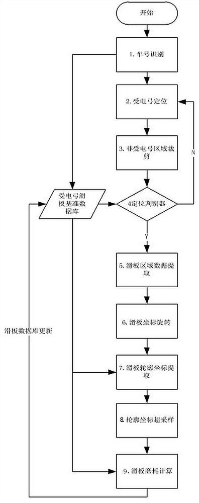
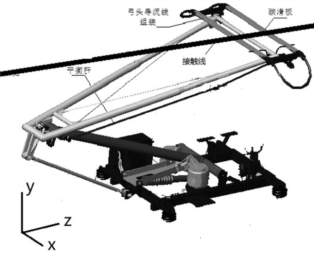
[0074] This embodiment discloses a method for measuring pantograph wear based on 3D imaging, such as figure 2 and 3 , in the imaging data based on the high-speed 3D imaging device, the pantograph and the catenary are discretized into three-dimensional data points containing three coordinates of X, Y, and Z. The original image is a grayscale image, which can be converted into a 2D edge profile. Or rendered as a three-dimensional image. In this scheme, one 3D imaging device captures half of the pantograph axis-symmetric line as the center, and the other 3D imaging device captures the other half of the pantograph, and the method of use is the same. Therefore, in this scheme The methods involved all take one 3D imaging unit as an example. During the long-term operation of the subway line, the pantograph skateboard will inevitably experience normal or abnormal wear, which is manifested in the imaging data as the subtraction of the y-coordinate value of the skateboard outline. Wh...

Embodiment 2

[0119] Further, corresponding to the wear measurement method in the above-mentioned embodiment 1, this embodiment also provides a pantograph wear measurement system based on 3D imaging, including:

[0120] The car number acquisition unit is set at the trackside and is used to acquire the car number image of the vehicle to be checked;

[0121] A reference profile acquisition unit, configured to identify the vehicle number image on the vehicle number image by using the OCR method, obtain the vehicle number of the vehicle to be detected, and retrieve the vehicle number corresponding to the vehicle to be detected in the pantograph slide reference database according to the vehicle number. datum profile history set;

[0122] The 3D imaging acquisition unit includes 2 3D imaging devices, the 2 3D imaging devices are located on the same vertical calibration plane and arranged along the horizontal direction, and are used to obtain the 3D point cloud data of the vehicle to be detected; ...


PUM


Abstract

The invention belongs to the technical field of train pantograph visual imaging detection, and discloses a pantograph wear measurement method and system based on 3D imaging, including a reference contour acquisition step, a pantograph area positioning step, a positioning discriminator discrimination step, a slide plate The area extraction step, the skateboard area rotation step, the skateboard contour coordinate extraction step, the contour coordinate oversampling step, and the skateboard wear calculation step are a method based on the imaging device of the high-speed 3D imaging device installed on the inner wall of the tunnel to obtain the vehicle roof and vehicle to be detected. The image data of the top equipment is used to locate the real-time position of the pantograph through the visual recognition method and compare it with the standard data to determine the wear condition of the pantograph bow head.

Description

technical field [0001] The invention belongs to the technical field of on-line detection of train pantographs, in particular to a method and system for measuring pantograph wear based on 3D imaging. Background technique [0002] In the design of electrified railways, the pantograph is used as the current receiving device of electrified vehicles, and the wear of the pantograph slide plate is one of the key factors affecting the pantograph-catenary relationship and the quality of current receiving. The function of the pantograph is to provide electric energy for the electric locomotive through the contact between the pantograph slide plate and the catenary contact wire. [0003] The evaluation of the state of the pantograph mainly refers to two state parameters: geometric parameters and dynamic parameters. Among them, the geometric parameters include the wear amount of the skateboard, the offset of the center line and the tilt of the bow head; the dynamic parameters are the c...

Claims


Application Information

Patent Timeline
Patent Type & Authority Patents(China)
IPC IPC(8): G01B11/24
CPCG01B11/24
Inventor 张志豪王瑞锋占栋李文宝黄成亮蒲继华
Owner CHENGDU TANGYUAN ELECTRICAL APPLIANCE
Features
  • R&D
  • Intellectual Property
  • Life Sciences
  • Materials
  • Tech Scout
  • Unparalleled Data Quality
  • Higher Quality Content
  • 60% Fewer Hallucinations
Learn More