Unmanned-aerial-vehicle-mounted double-target-plate visibility detection method

A detection method and target board technology, which are applied in the field of visibility detection of aerial drones with dual target boards, can solve problems such as narrow application range, influence on visibility detection accuracy, background interference, etc., and achieve high-precision visibility detection and visibility. The effect of detection and accurate measurement

Inactive Publication Date: 2020-09-01
NAT UNIV OF DEFENSE TECH
View PDF4 Cites 1 Cited by
  • Summary
  • Abstract
  • Description
  • Claims
  • Application Information

AI Technical Summary

Problems solved by technology

In this measurement method, the interference of background objects is serious and the scope of application is narrow. The uneven distribution of clouds in the sky, reflections on the ground, and reflectors in the direction of the camera's line of sight will all affect the accurate extraction of sky background brightness, and then affect the detection accuracy of visibility. Therefore, it is necessary to study the visibility detection method that can improve the measurement accuracy of the background sky brightness, or propose a new visibility detection method that is not affected by the sky background brightness, in order to improve the accuracy of the digital camera method for visibility detection

Method used


Image

  • Unmanned-aerial-vehicle-mounted double-target-plate visibility detection method
  • Unmanned-aerial-vehicle-mounted double-target-plate visibility detection method
  • Unmanned-aerial-vehicle-mounted double-target-plate visibility detection method

Examples


Embodiment Construction

[0019] The specific implementation manners of the present invention will be further described in detail below in conjunction with the accompanying drawings.

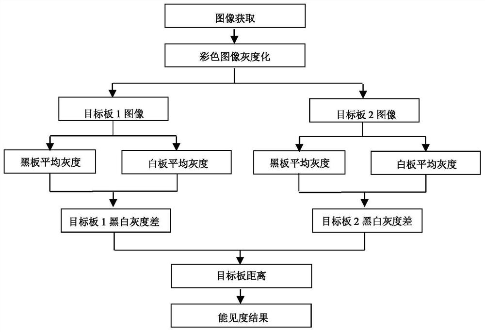
[0020] In this embodiment, the UAV-borne image acquisition unit, the UAV-borne target board unit and the ground data processing terminal unit are set; the UAV-borne image acquisition unit is one or more, and each UAV-borne image acquisition unit is configured Two drone-mounted target board units; the drone-mounted image acquisition unit is composed of a miniature multi-rotor drone equipped with a digital camera, which captures images in the target direction area in real time, and wirelessly transmits the acquired images to The ground data processing terminal unit; the UAV-borne target board unit is composed of a miniature multi-rotor UAV carrying a corresponding target black body board, and maintains the same vertical height with the camera, and is separated from a certain baseline length in the horizontal direction; the ...


PUM


Abstract

The invention discloses an unmanned-aerial-vehicle-mounted double-target-plate visibility detection method. The method comprises the steps: forming an unmanned-aerial-vehicle-mounted image collectionunit through employing an unmanned-aerial-vehicle-mounted digital camera, and forming unmanned-aerial-vehicle-mounted target plate units through employing unmanned-aerial-vehicle-mounted target plates; enabling an unmanned-aerial-vehicle-mounted image acquisition unit and the two unmanned-aerial-vehicle-mounted target plate units to fly at the same height in the air, capturing images of the two target plates in real time by using a digital camera, calculating average gray values of black and white parts on each target plate on the images, and substitutes the average gray values into a visibility measurement model to obtain an atmospheric horizontal visibility value at the vertical height. According to the method, a problem that a target originally fixed on a foundation is influenced by obstacles and background sky brightness as well as a problem that the measured value of an existing instrument cannot represent the local actual condition when the atmospheric visibility is uneven can besolved; and high-precision real-time measurement can be performed on visibility weather with different vertical heights, different horizontal orientations and dynamic changes by utilizing the maneuvering flexibility and the hovering operation mode of the unmanned aerial vehicle.

Description

technical field [0001] The invention belongs to the fields of meteorology and electronics, and in particular relates to a visibility detection method suitable for a dual-target board carried by an aerial unmanned aerial vehicle. Background technique [0002] Atmospheric visibility is an important weather and meteorological observation element, which seriously restricts aviation, navigation, road traffic and military activities. At present, the commonly used atmospheric visibility measurement instruments are mainly detectors based on scattering and transmission technology systems. With the rapid development of imaging and data processing technologies, the digital camera method is also widely used in visibility monitoring research due to its advantages of low cost, simple operation, and low site requirements. However, most of the existing digital video monitoring visibility technologies are based on the brightness contrast method to capture images of a single target and the b...

Claims


Application Information

Patent Timeline
Patent Type & Authority Applications(China)
IPC IPC(8): G01W1/00G01C11/00
CPCG01C11/00G01W1/00Y02A90/10
Inventor 王敏周树道杨忠郑崇伟黎鑫叶松洪梅王辉赞贾赟张阳春宋海润李庆辉
Owner NAT UNIV OF DEFENSE TECH
Why Eureka
Try Eureka