
Jig for buckling and installing side key fingerprint BTB connector

A technology of connectors and side keys, applied in the field of electronic equipment assembly auxiliary fixtures, can solve the problems of poor overall quality stability of products, increase the difficulty of product quality control, and uncontrollable angle and force of buckle, so as to reduce buckle The risk of bad or even buckle damage, reduce the risk of being torn, the effect of simple and reliable structure

Active Publication Date: 2020-09-01
OPPO CHONGQING INTELLIGENT TECH CO LTD
View PDF9 Cites 0 Cited by
  • Summary
  • Abstract
  • Description
  • Claims
  • Application Information

AI Technical Summary

Problems solved by technology

On the one hand, the side key fingerprint BTB connector has no auxiliary tools during the assembly (fastening) process, and it is fastened manually, which is very inconvenient to operate; the process of pulling the side key fingerprint FPC fastening is easy to cause the side key fingerprint module to be removed from the middle frame. On the other hand, the angle and strength of the buckle are uncontrollable, and the BTB connector has the risk of not buckling in place or even being broken.
Because each worker's operation mode or work proficiency is different, the assembly quality of the product is uneven, and the quality of the product assembled by different assembly batches or different workers or the same worker in different states is different, resulting in the overall Poor quality stability increases the difficulty of product quality control

Method used


Image

  • Jig for buckling and installing side key fingerprint BTB connector
  • Jig for buckling and installing side key fingerprint BTB connector
  • Jig for buckling and installing side key fingerprint BTB connector

Examples


Embodiment Construction

[0019] The present invention will be described in further detail below in conjunction with the accompanying drawings and embodiments. In particular, the following examples are only used to illustrate the present invention, but not to limit the scope of the present invention. Likewise, the following embodiments are only some but not all of the embodiments of the present invention, and all other embodiments obtained by persons of ordinary skill in the art without creative efforts fall within the protection scope of the present invention.

[0020] Reference herein to an "embodiment" means that a particular feature, structure, or characteristic described in connection with the embodiment can be included in at least one embodiment of the present invention. The occurrences of this phrase in various places in the specification are not necessarily all referring to the same embodiment, nor are separate or alternative embodiments mutually exclusive of other embodiments. It is understoo...


PUM


Abstract

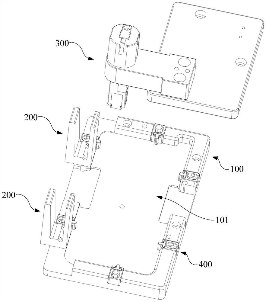
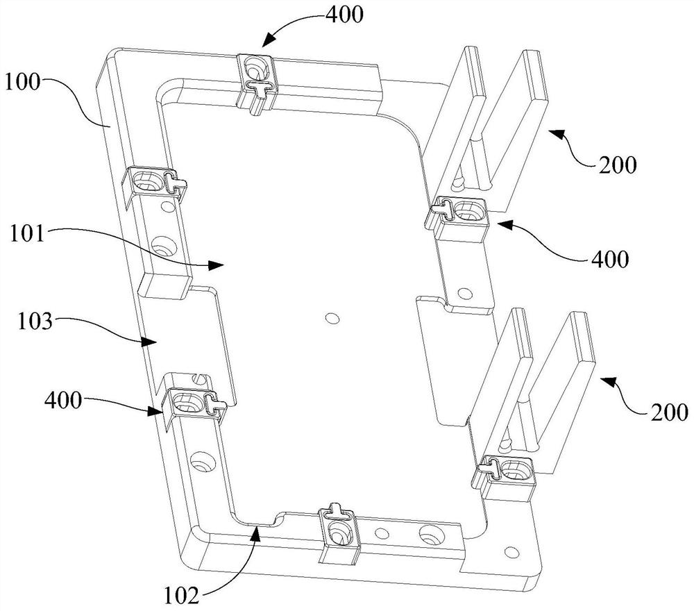
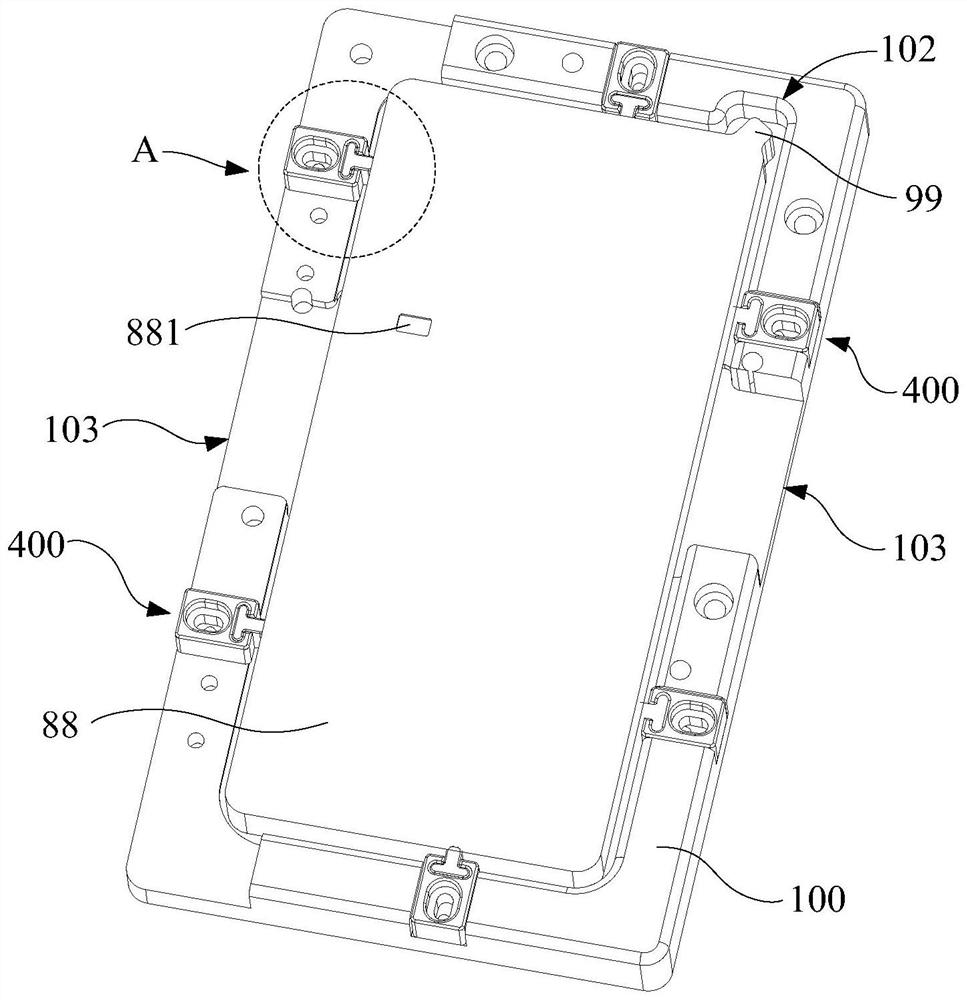
The invention provides a jig for buckling and installing a side key fingerprint BTB connector. The jig comprises a bottom plate, a supporting frame and a pressing assembly, the bottom plate is provided with an accommodating groove, and the accommodating groove is used for accommodating a circuit board of an electronic device or a semi-finished product assembly comprising the circuit board. The supporting frame is fixedly arranged at the edge of the bottom plate, is adjacent to the accommodating groove and is used for supporting a middle frame assembly, and the pressing assembly is used for pressing a first connecting terminal and a second connecting terminal of the BTB connector in an alignment state, so that the first connecting terminal and the second connecting terminal of the BTB connector are conducted through an electric signal. According to the jig, the moving space of a side key fingerprint FPC is reduced by pre-fixing the middle frame, so that the side key fingerprint is prevented from being pulled to fall off from the middle frame, and the risk that the FPC is torn is reduced; in addition, the connecting terminals at the two sides of the BTB connector are pressed throughthe pressing assembly, so that on one hand, the uniformity of the assembling quality can be guaranteed, and on the other hand, the risk that the BTB connector is poor in buckling and even damaged canbe greatly reduced.

Description

technical field [0001] The invention relates to the technical field of an auxiliary jig for assembly of electronic equipment, in particular to a jig for fastening and installing a side key fingerprint BTB connector. Background technique [0002] With the fierce competition and rapid development of the mobile phone and other electronic equipment industries, more and more structural and design innovations have been brought about, and the design of the side key fingerprint is one of them. The technical solution of the side button fingerprint is specifically to combine the power button and the fingerprint button into one, which reduces the cost while reducing the number of openings in the fuselage, and brings consumers a new experience. At present, the assembly method of the side key fingerprint is generally as follows: the assembler holds the middle frame (with the side key fingerprint module already installed) with one hand, pulls the side key fingerprint FPC with the other ha...

Claims


Application Information

Patent Timeline
Patent Type & Authority Applications(China)
IPC IPC(8): H01R43/26
CPCH01R43/26
Inventor 杨威
Owner OPPO CHONGQING INTELLIGENT TECH CO LTD
Learn More