Immersed cooling device

A cooling device, immersion technology, applied in the direction of cooling/ventilation/heating renovation, electrical components, electrical equipment structural parts, etc. cost saving effect

Active Publication Date: 2020-09-01
WARECONN TECH SERVICE (TIANJIN) CO LTD
View PDF10 Cites 3 Cited by
  • Summary
  • Abstract
  • Description
  • Claims
  • Application Information

AI Technical Summary

Problems solved by technology

In this way, the insulating cooling liquid is delivered to the device where the server is placed through the cooling device, and the transportation distance between the two i

Method used


Image

  • Immersed cooling device
  • Immersed cooling device
  • Immersed cooling device

Examples


no. 1 example

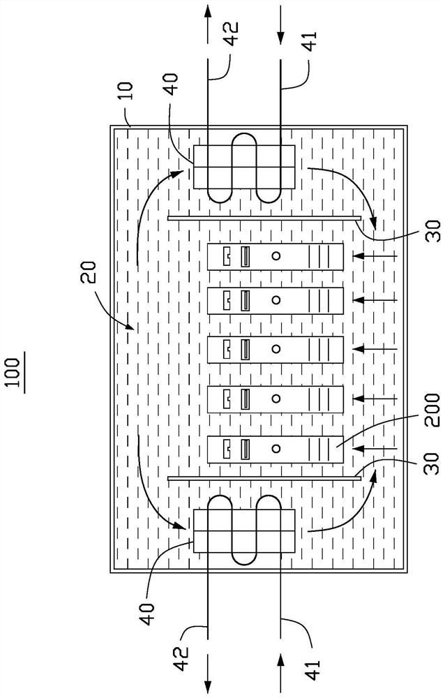
[0036] See figure 1 This embodiment provides an immersion cooling device 100 for cooling the electronic device 200. Further, the electronic device 200 is a server. It can be understood that, in other embodiments, the electronic device 200 may also be other devices that need to be cooled.

[0037] See figure 1 The immersion cooling device 100 includes a tank 10 for holding an insulating cooling liquid 20 to soak the electronic device 200. The immersion cooling device 100 further includes a partition 30 and a heat exchanger 40. The partition 30 is arranged in parallel with the electronic device 200, the partition 30 and the heat exchanger 40 are arranged inside the tank 10, and the heat exchanger 40 is placed in the tank 10 The electronic devices 200 are respectively disposed on opposite sides of the partition 30, and the partition 30 is used to guide the flow direction of the insulating cooling liquid 20.

[0038] The insulating cooling liquid 20 flows in different directions due...

no. 2 example

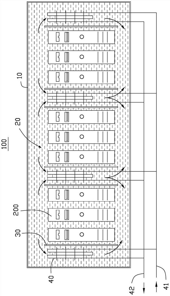
[0048] See figure 2 The structure of the second embodiment is basically similar to that of the first embodiment. However, the difference between the second embodiment and the first embodiment is that the immersion cooling device 100 is provided with multiple sets of partitions 30 and heat exchangers 40. Wherein, the cold water port 41 and the hot water port 42 on the plurality of heat exchangers 40 are connected in series to form a connected pipeline, which passes through the heat exchanger 40 on the edge of the tank 10 The cold water port 41 and the hot water port 42 are connected to an external supply device.

[0049] Through the above-mentioned serial communication mode, the cold water port 41 and the hot water port 42 of the heat exchanger 40 do not need to be connected to the external supply device separately, which simplifies the connection between the submerged cooling device 100 and the external supply device. The connection between.

no. 3 example

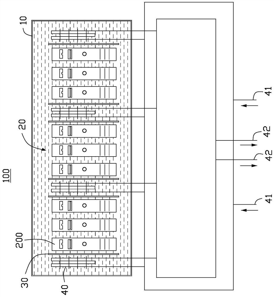
[0051] See image 3 The structure of the third embodiment is basically similar to that of the second embodiment. However, the difference between the third embodiment and the second embodiment is that the cold water ports 41 and hot water ports 42 on the multiple heat exchangers 40 are connected in series, and then the cold water ports 41 that form a pipeline after being connected in series are designed as At the same time, the hot water port 42 that forms a pipeline after being connected in series is also designed in a ring shape. The cold water port 41 and the hot water port 42 on the two heat exchangers 40 near the edge of the tank 10 are connected to an external supply device.

[0052] After the cold water port 41 and the hot water port 42 on the heat exchanger 40 are connected in series, a ring design is adopted. When one of the heat exchangers 40 fails, the cooling water provided by the external supply device can also flow in or out from the other direction of the annular d...


PUM


Abstract

An immersed cooling device includes a tank barrel containing an insulating coolant to soak an electronic device, a bulkhead, and a heat exchanger. The partition plate and the heat exchanger are arranged in the tank barrel, the heat exchanger and the electronic device placed in the tank barrel are arranged at the two opposite sides of the partition plate respectively, and the partition plate is used for guiding the flowing direction of insulating cooling liquid. After flowing through the electronic device, the insulating cooling liquid with heat flows to the upper part of the tank barrel through the guide of the partition plate and passes through the heat exchanger, and the insulating cooling liquid subjected to heat exchange is guided by the partition plate to flow to the lower part of thetank barrel and flow to the electronic device. According to the immersed cooling device provided by the invention, the heat exchanger is directly arranged in the tank barrel, so that the structure ofthe device is simplified.

Description

Technical field [0001] The invention relates to the technical field of computer cooling, in particular to an immersion cooling device. Background technique [0002] As server functions become more powerful, the requirements for server cooling have gradually become stricter. Under increasingly strict requirements, immersing the server in a device containing a non-conductive liquid has become the main solution. At the same time, it is necessary to install a cooling device to deliver insulating coolant to the device where the server is placed. The server is cooled, and the delivery of the coolant requires the push of a pump. As a result, the cooling device is used to deliver insulating coolant to the device on which the server is placed. The distance between the two increases the amount of insulating coolant, which increases the cost of cooling the server. At the same time, it requires pumping to reduce Cooling efficiency. Summary of the invention [0003] In view of this, it is n...

Claims


Application Information

Patent Timeline
IPC IPC(8): H05K7/20
CPCH05K7/20763H05K7/20236H05K7/20781Y02D10/00H05K7/20772H05K7/20272
Inventor 毛之成张志鸿傅彦钧张耀廷张力文魏钊科
Owner WARECONN TECH SERVICE (TIANJIN) CO LTD
Why Eureka
Try Eureka