
Trimming device

A technology of accommodating grooves and mounting seats, which is applied to the details of milling machine equipment, metal processing equipment, milling machine equipment, etc., can solve the problems of delamination of the trimming surface, large vibration, thermal damage, etc., and achieve the effect of ensuring the quality of trimming

Inactive Publication Date: 2020-09-04
COMAC +1
View PDF7 Cites 0 Cited by
  • Summary
  • Abstract
  • Description
  • Claims
  • Application Information

AI Technical Summary

Problems solved by technology

Since this method does not limit the milling path of the milling cutter, and the composite material itself is difficult to process, it vibrates greatly during trimming, which can easily cause damage to the milling cutter and irregular shape of the trimmed part, and due to the shape of the trimmed part Irregular and repeated trimming makes the trimmed surface of composite materials prone to delamination and thermal damage, resulting in product defects

Method used


Image

  • Trimming device
  • Trimming device
  • Trimming device

Examples


Embodiment Construction

[0036] In order to make the technical problems solved by the present invention, the technical solutions adopted and the technical effects achieved clearer, the technical solutions of the embodiments of the present invention will be further described in detail below in conjunction with the accompanying drawings. Obviously, the described embodiments are only the technical solutions of the present invention. Some, but not all, embodiments. Based on the embodiments of the present invention, all other embodiments obtained by those skilled in the art without creative efforts fall within the protection scope of the present invention.

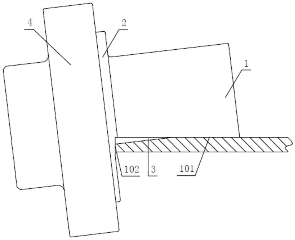
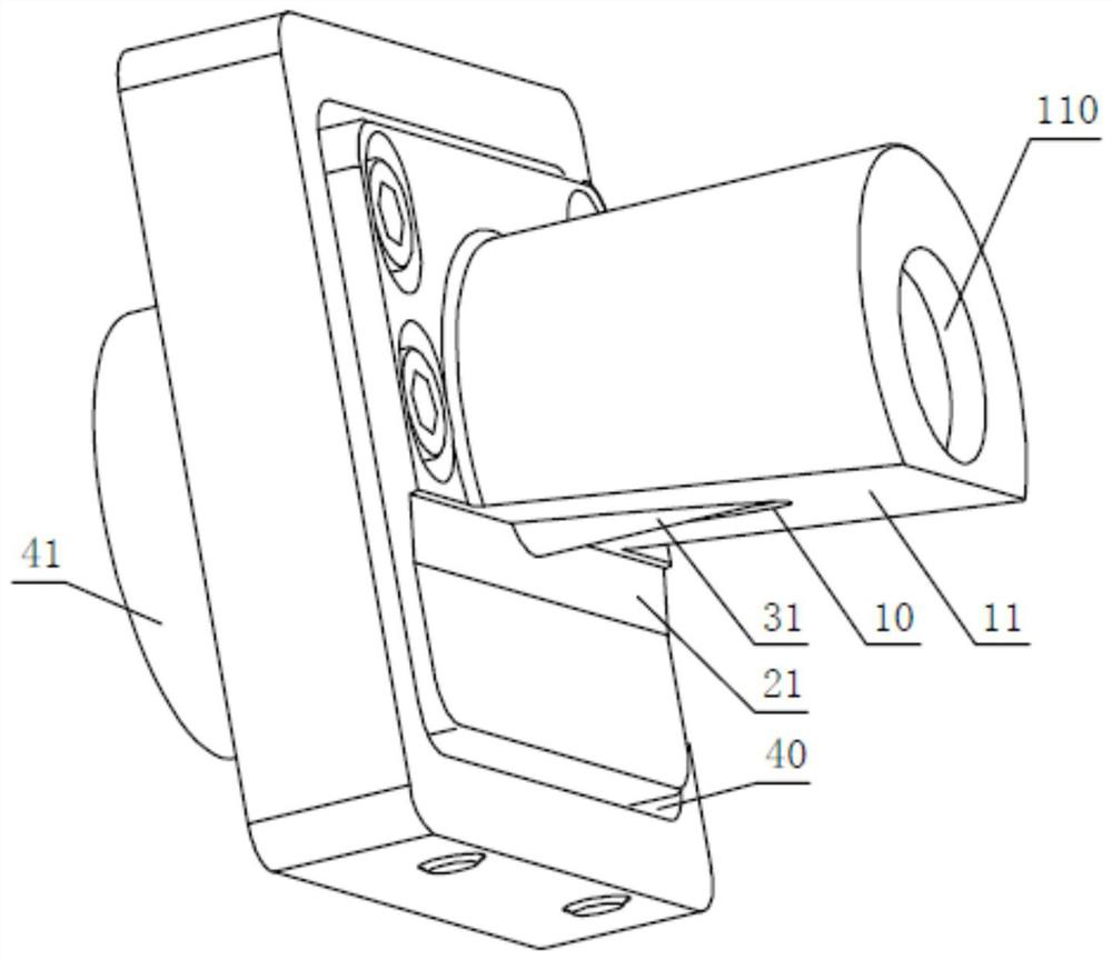
[0037] see figure 1 , figure 2 and image 3 , the present embodiment provides a trimming device for trimming an edge 100 of a workpiece, the workpiece has a first side 101 of the edge 100 and a second side 102 of the edge 100, the first side 101 and the second side 102 are two adjacent surfaces, and the edge 100 is the boundary edge between the fir...


PUM


Abstract

The invention relates to the technical field of material molding, and discloses a trimming device. The trimming device is used for trimming an edge of a workpiece, and includes a profiling pipe used for abutting against a first side face of the edge, a master plate connected to one end of the profiling pipe and used for abutting against a second side face of the edge, and a cutter that extends from the profiling pipe. In the trimming device of the invention, the cutter extends out of the profiling pipe to trim the edge of the workpiece, during trimming and processing, the profiling pipe abutsagainst the first side face of the edge, the master plate abuts against the second side face of the edge, and so, a trimming path of the cutter is restricted, and the trimming quality and the servicelife of the cutter are ensured.

Description

technical field [0001] The invention relates to the technical field of material forming, in particular to a trimming device. Background technique [0002] In the molding process of composite materials, it is usually necessary to process transition slopes such as chamfers on the edges of composite material parts to facilitate subsequent assembly and use. [0003] Constrained by the existing composite material forming technology, the transition slope on the edge cannot be formed at one time, and must be specially trimmed and cut in the later stage. The bevel trimming of the edge of the composite material part is currently commonly used to install the milling cutter on the air drill to directly trim the edge of the composite material part. Since this method does not limit the milling path of the milling cutter, and the composite material itself is difficult to process, it vibrates greatly during trimming, which can easily cause damage to the milling cutter and irregular shape ...

Claims


Application Information

Patent Timeline
Patent Type & Authority Applications(China)
IPC IPC(8): B23C3/12
CPCB23C3/12
Inventor 张发品田冬凤刘立陈凯云一珅倪冠晨
Owner COMAC
Learn More