Multi-station machining platform
A processing platform and multi-station technology, applied to workbenches, manufacturing tools, etc., can solve problems such as inability to adapt to the operation of various processing tasks, and achieve the effect of improving stability and increasing the support range
- Summary
- Abstract
- Description
- Claims
- Application Information
AI Technical Summary
Problems solved by technology
Method used
Image

Examples
specific Embodiment approach 1
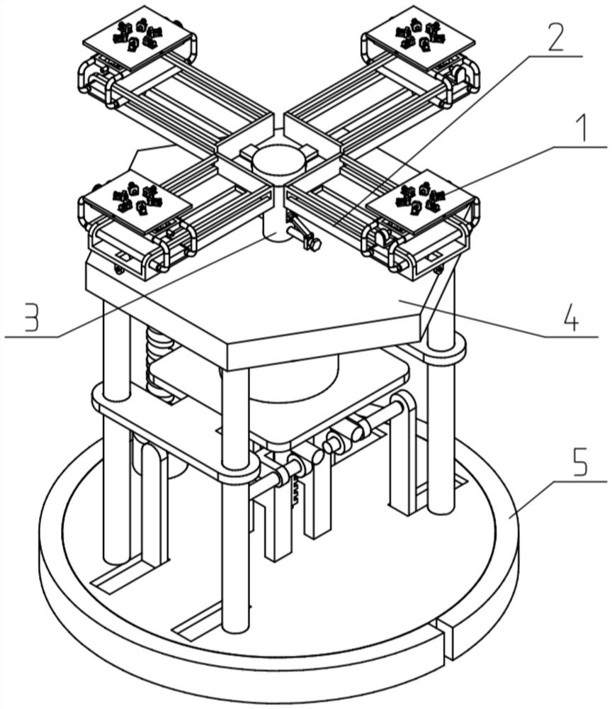
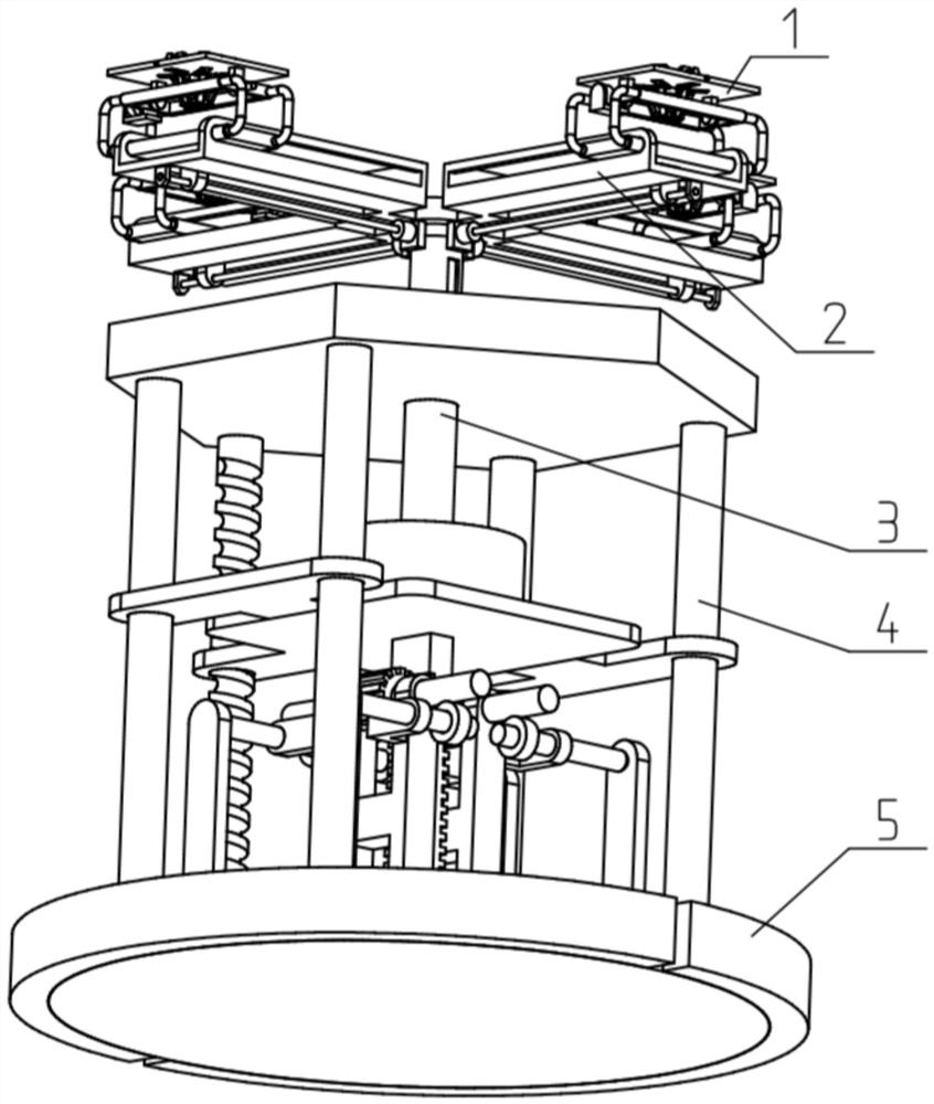
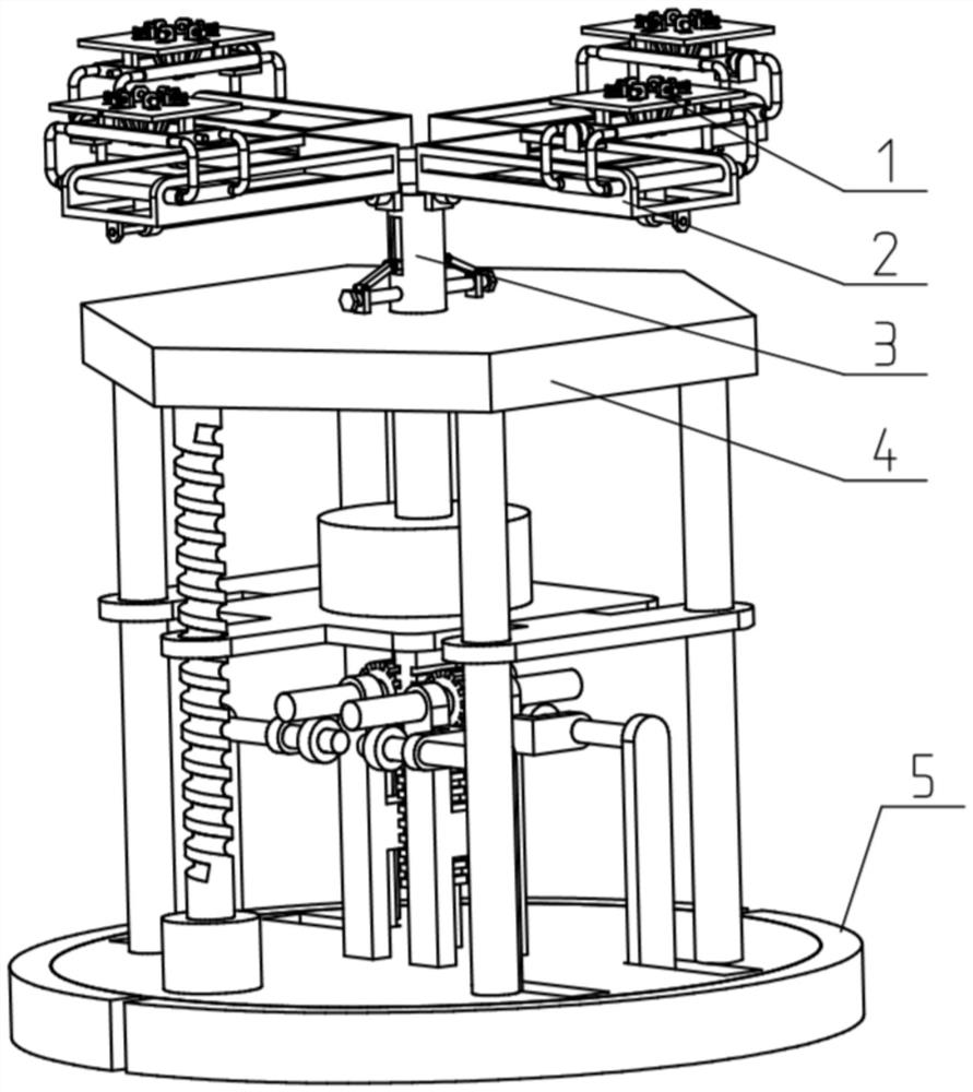
[0038] Such as Figure 1-12 As shown, the multi-station processing platform includes a tooling unit 1, a turret unit 2, a drive unit 3 and a support unit 4; the tooling unit 1 includes a tooling seat plate 101, a swing connecting plate 102, a rotating shaft 103, a bracket 104 and Servo motor one 105; the bottom of the tooling seat plate 101 is fixedly connected to the two swing connecting plates 102, and the two swing connecting plates 102 are movably connected to the two ends of the bracket 104 through a rotating shaft 103 respectively. end; the output shaft of the servo motor one 105 fixed on the bracket 104 is fixedly connected with one of the rotating shafts 103;
[0039] The bracket 104 is movably connected to the turret unit 2 ; the turret unit 2 is fixedly connected to the driving unit 3 ; and the driving unit 3 is fixedly connected to the supporting unit 4 .
[0040] The interior of the present invention is provided with a drive unit 3 that can drive the tooling unit ...
specific Embodiment approach 2
[0042] Such as Figure 1-12 As shown, the tooling seat plate 101 includes a seat plate body 101A, a guide column 101B, a sliding top block 101C, a push-pull connecting plate 101D, a push-pull seat 101E, a screw rod one 101F and a servo motor two 101G; the servo motor two 101G is fixed In the middle of the bottom end of the seat plate body 101A; six rectangular slideways are uniformly arranged around the seat plate body 101A; one guide column 101B is respectively fixed in the six rectangular slideways; One of the sliding top blocks 101C is slidably fitted in the track, and the six sliding top blocks 101C are slidably fitted on the six guide posts 101B; the lower ends of the six sliding top blocks 101C are respectively connected to one of the push-pull connecting plates The upper end of 101D and the lower ends of the six push-pull connecting plates 101D are rotatively connected to the push-pull seat 101E; The shaft device is connected with the output shaft of the servo motor 2 ...
specific Embodiment approach 3
[0044] Such as Figure 1-12 As shown, the tooling seat plate 101 also includes an adjusting bolt 101H, an adjusting rotary block 101I, and a hemispherical pressing head 101J; one of the six sliding jacking blocks 101C is threadedly fitted with one of the adjusting bolts 101H, and the six The inner and outer ends of the adjusting bolt 101H are respectively fixedly connected with the hemispherical pressing head 101J and the adjusting rotary block 101I. Turning the adjusting rotary block 101I to drive the adjusting bolt 101H to rotate can change the contact position between the adjusting bolt 101H and the sliding top block 101C, and adjust the distance between the hemispherical top pressure head 101J and the sliding top block 101C, which is convenient for processing different shapes of workpieces to be processed used when.
PUM
 Abstract
Description
Claims
Application Information
 - R&D
- Intellectual Property
- Life Sciences
- Materials
- Tech Scout
- Unparalleled Data Quality
- Higher Quality Content
- 60% Fewer Hallucinations
Browse by: Latest US Patents, China's latest patents, Technical Efficacy Thesaurus, Application Domain, Technology Topic, Popular Technical Reports.
© 2025 PatSnap. All rights reserved.Legal|Privacy policy|Modern Slavery Act Transparency Statement|Sitemap|About US| Contact US: help@patsnap.com