Industrial robot composite clamp

A technology of industrial robots and fixtures, applied in the direction of manufacturing tools, manipulators, etc., can solve the problems of damaged fixtures, occupying a lot of space, and workers being injured, and achieve the effect of reducing the overall space occupied

Inactive Publication Date: 2020-09-04
江苏省泰兴中等专业学校
View PDF6 Cites 0 Cited by
  • Summary
  • Abstract
  • Description
  • Claims
  • Application Information

AI Technical Summary

Problems solved by technology

[0003] During the use of industrial robots, it is often necessary to install a composite fixture on the movable arm of the industrial robot to clamp the workpiece and move the workpiece; in the process of clamping some larger workpieces Generally, it is necessary to use larger composite fixtures; although these larger fixtures can easily clamp large workpieces, when the industrial robot is idle, the claws of these fixtures will protrude outward, occupying a large area. During the process of workers walking in the factory, they are likely to accidentally hit these fixtures, or when carrying objects, the objects will hit these fixtures, which may cause workers to be injured or the fixtures to be damaged.

Method used


Image

  • Industrial robot composite clamp
  • Industrial robot composite clamp
  • Industrial robot composite clamp

Examples


Embodiment 1

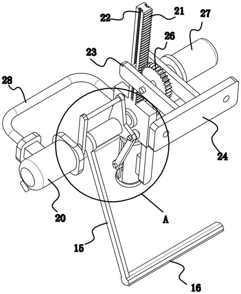
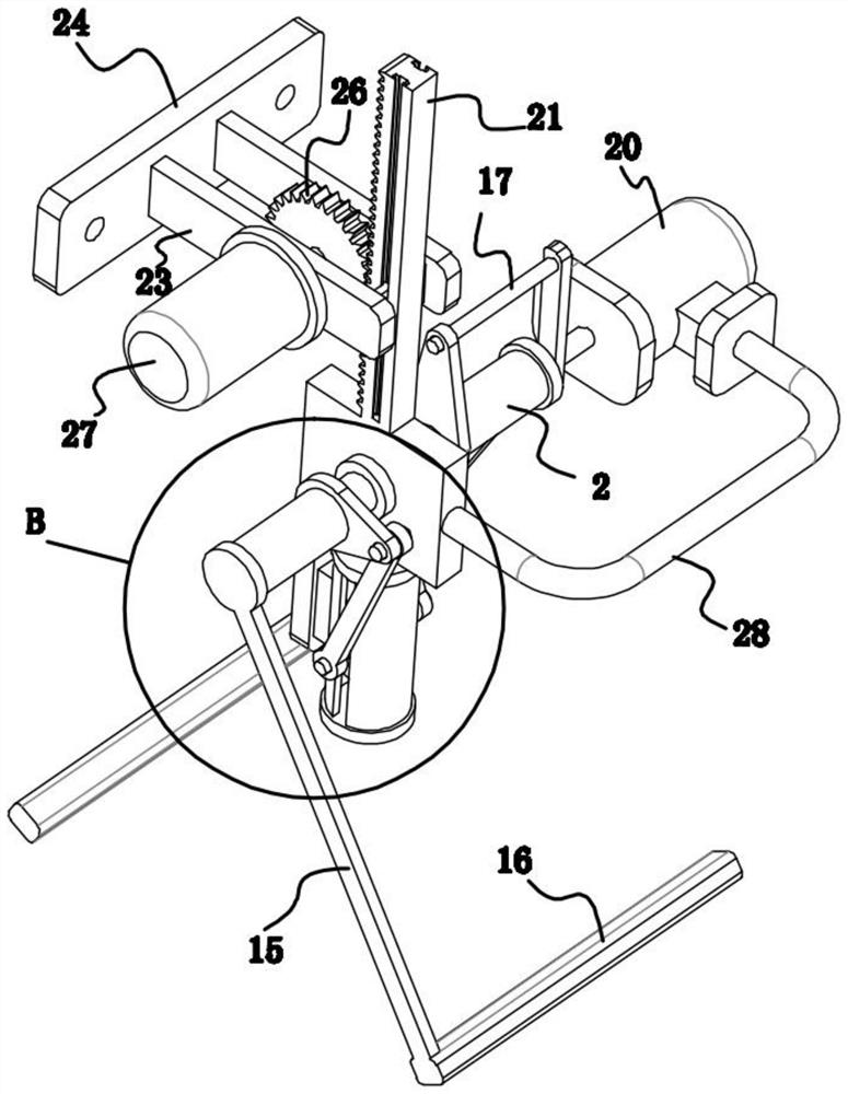
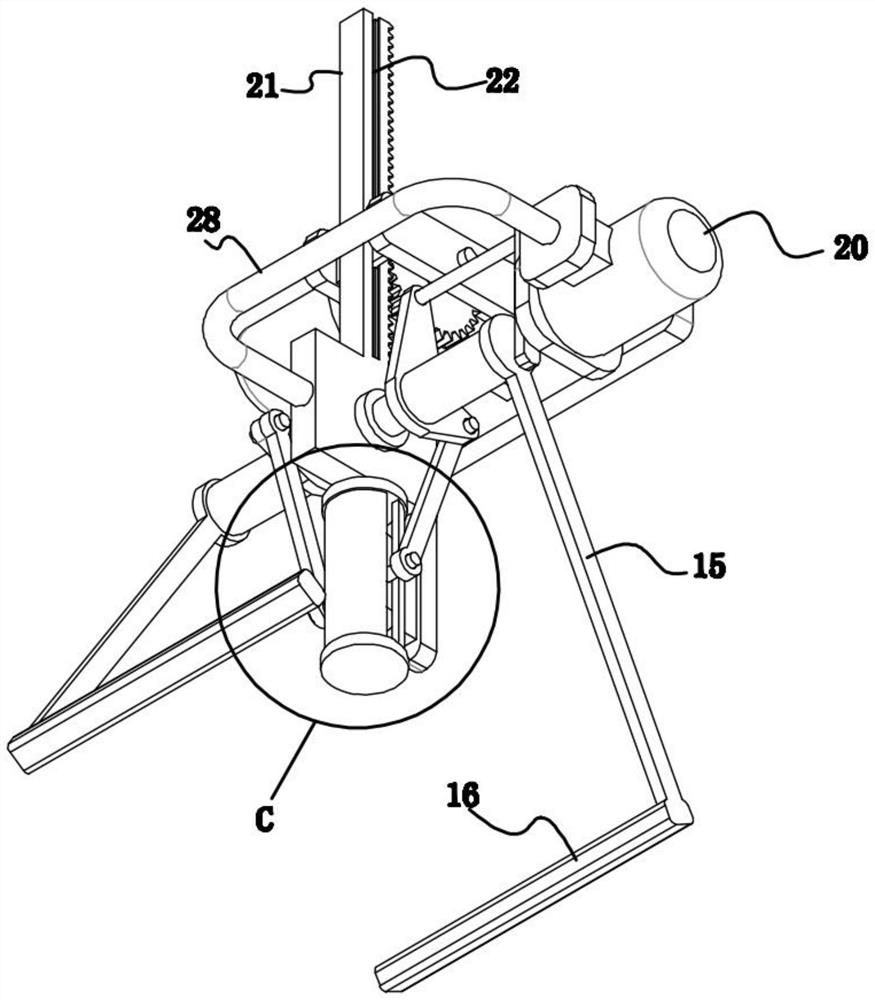
[0023] refer to Figure 1-7 , an industrial robot composite fixture, including a fixed plate 1, a vertically arranged central axis 19 is fixedly installed on the fixed plate 1, and both ends of the central axis 9 extend outward until they pass through the fixed plate 1, and the outer end of the central axis 9 The first sub-shaft 2 and the second sub-shaft 5 coaxially arranged therewith are respectively rotatably mounted on them, and a rod body 15 is fixedly installed on the outer ends of the first sub-shaft 2 and the second sub-shaft 5 , and the rod body 15 A splint 16 is fixedly installed on the inner surface of each, the first sub-shaft 2 and the second sub-shaft 5 are connected to the same driving module by transmission, and a lifting module is fixedly installed on the top of the fixed plate 1 .

[0024] The driving module includes a driving plate 3, a first connecting plate 4, a second connecting plate 6, a transmission mechanism, and a first driving mechanism. A connecti...

Embodiment 2

[0029] refer to Figure 1-7 As another preferred embodiment of the present invention, the difference from Embodiment 1 is that the lifting module includes a rack 21 and a second driving mechanism, the top of the fixed plate 1 is fixedly equipped with a rack 21, and the rack 21 is uploaded and connected to a second drive mechanism. Two driving mechanisms. The second drive mechanism comprises chute 22, side plate 23, mounting plate 24, drive shaft 25, gear 26, second motor 27, all has chute 22 along its length direction on two corresponding sides of rack 21, every A slide block can be slidably installed in each of the chute 22, and a side plate 23 is fixedly connected to each slide block, and the two side plates 23 are arranged parallel to each other, and the same-side end between the two side plates 23 A mounting plate 24 is fixedly installed, and a drive shaft 25 is installed rotatably between the two side plates 23. A gear 26 coaxially arranged with it is fixedly installed o...


PUM


Abstract

The invention relates to the technical field of industrial robots, in particular to an industrial robot composite clamp. A vertically-arranged middle shaft is fixedly mounted on a fixing plate, and the two ends of the middle shaft extend outwards till penetrating through the fixing plate. A first auxiliary shaft and a second auxiliary shaft which are coaxial with the middle shaft are rotatably mounted at the tail end of the outer side of the middle shaft correspondingly. Rod bodies are fixedly mounted at the tail ends of the outer sides of the first auxiliary shaft and the second auxiliary shaft correspondingly. Clamping plates are fixedly mounted on the inner side surfaces of the rod bodies correspondingly. The first auxiliary shaft and the second auxiliary shaft are in transmission connection with the same driving module. A lifting module is fixedly mounted at the top end of the fixing plate. When the industrial robot composite clamp is not used, the two rod bodies and the clamping plates can be retracted inwards, and thus the overall occupied space of the industrial robot composite clamp is reduced.

Description

technical field [0001] The invention relates to the technical field of industrial robots, in particular to a composite clamp for industrial robots. Background technique [0002] An industrial robot is a multi-joint manipulator or a multi-degree-of-freedom machine device for the industrial field. It can perform work automatically and is a machine that realizes various functions by its own power and control capabilities. It can be commanded by humans or run according to pre-programmed programs. Modern industrial robots can also act according to the principles and programs formulated by artificial intelligence technology. [0003] During the use of industrial robots, it is often necessary to install a composite fixture on the movable arm of the industrial robot to clamp the workpiece and move the workpiece; in the process of clamping some larger workpieces Generally, it is necessary to use larger composite fixtures; although these larger fixtures can easily clamp large workpie...

Claims


Application Information

Patent Timeline
IPC IPC(8): B25J19/00
CPCB25J19/00
Inventor 苏辉李晓男丁九峰陈爱午何兵王文鑫沈丹萍唐睿炎张凡
Owner 江苏省泰兴中等专业学校
Why Eureka
Try Eureka