
A multirotor aircraft that is adapted for vertical take-off and landing (VTOL)

A multi-rotor aircraft and vertical take-off technology, applied in vertical take-off and landing aircraft, unmanned aircraft, aircraft, etc., can solve the problems of reduced structural efficiency, reduced structural weight efficiency, safety risks, etc., to reduce structural load, The effect of improving ground stability

Active Publication Date: 2020-09-04
空客城市移动有限公司
View PDF72 Cites 0 Cited by
  • Summary
  • Abstract
  • Description
  • Claims
  • Application Information

AI Technical Summary

Problems solved by technology

[0009] In any case, the main disadvantage of conventional VTOL multirotor aircraft is the lack of a secure boarding area that would allow the safe operation of the aircraft without exposure to adjacently located substantially lift-generating thrust generating units. And freely enter and exit the corresponding passenger compartment of the designated VTOL multi-rotor aircraft for boarding or emergency departure
Furthermore, in conventional VTOL multirotor aircraft there is often a difference between the dispersed lift and the concentrated mass due to the low-interaction multirotor setup, which induces large load levels on the corresponding aircraft structure, thus reducing the Structural Weight Efficiency
Furthermore, the placement of lifting surfaces (e.g., wings) and thrust generating units in front of the fuselage typically results in a large overhead mass, which results in the need for a strong frame inside the fuselage for safety requirements in emergency landing or crash situations, This results in an additional heavily loaded structure and an associated reduction in structural efficiency
In addition, the lift or forward thrust generating units are usually arranged such that their respective rotor disks impact the aircraft's nacelle, which leads to serious safety risks in the event of blade loss, thus further requiring protection for passengers and further adversely affecting weight efficiency
Finally, many conventional VTOL multicopters use undesired battery locations within the central fuselage close to the passengers, i.e. behind, below or next to the nacelle, which constitutes a serious problem in the event of a sudden battery fire during flight or after impact. security burden

Method used


Image

  • A multirotor aircraft that is adapted for vertical take-off and landing (VTOL)
  • A multirotor aircraft that is adapted for vertical take-off and landing (VTOL)
  • A multirotor aircraft that is adapted for vertical take-off and landing (VTOL)

Examples


Embodiment Construction

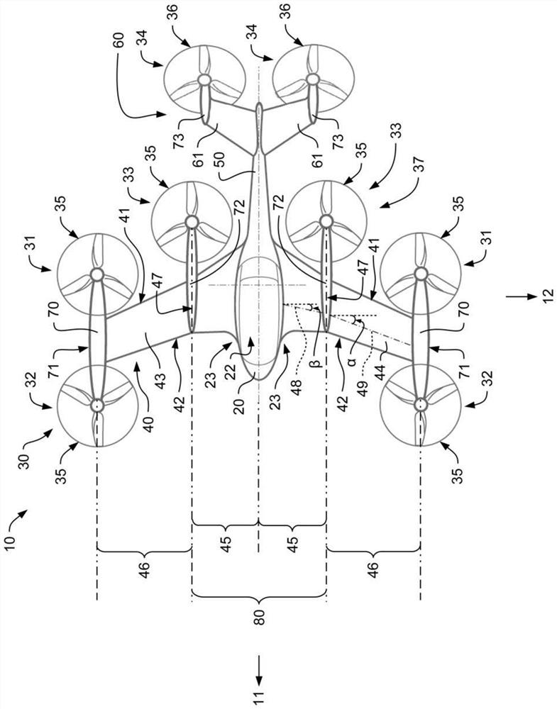
[0055] figure 1 An exemplary multi-rotor aircraft 10 is shown which is adapted for vertical takeoff and landing and is therefore provided with an array of thrust generating units 30 which in operation generate thrust to generate lift and forward thrust. The multi-rotor aircraft 10 is referred to as "VTOL multi-rotor aircraft 10" below.

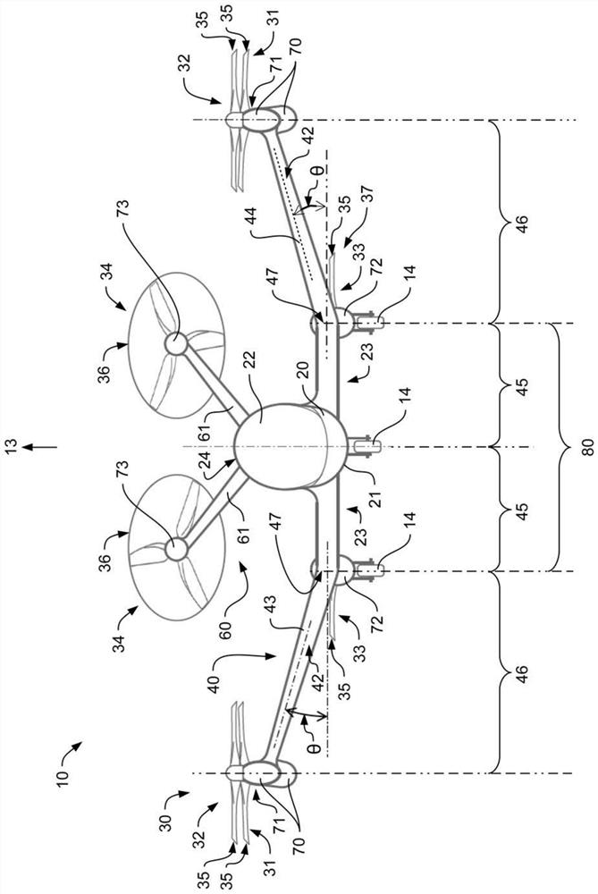
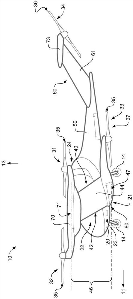
[0056] According to one aspect, the VTOL multirotor aircraft 10 is adapted to transport passengers and exemplarily includes forming a cabin ( figure 2 22) in the fuselage 20. Fuselage 20 may be connected to any suitable landing gear, such as skid or wheeled landing gear (e.g., figure 2 The landing gear in 14). For example, a single tailboom 50 is connected to and thus protrudes from the fuselage 20 , and an empennage 60 is provided at the rear portion of the tailboom 50 and is mounted to the tailboom 50 .

[0057] More specifically, fuselage 20 preferably defines a boarding area 23 adapted at least to enable easy and safe boarding of pas...


PUM


Abstract

A multirotor aircraft 10 that is adapted for vertical take-off and landing comprises a fuselage 20, a thrust producing unit assembly 30 that is provided for producing thrust in operation, and a forward-swept wing 40 that comprises a portside half wing 43 and a starboard side half wing 44. Each one of the portside and starboard side half wings 43, 44 comprises an inboard section 45 that is connected to the fuselage 20 and an outboard section 46 that forms a wing tip 71. The inboard sections 45 of the portside and starboard side half wings 43, 44 form a central wing region 80. The portside and starboard side half wings 43, 44 are respectively connected in the region of their wing tips 71 to an associated outboard wing pod 70 that supports at least two non-tiltably mounted thrust producing units 31, 32 of the thrust producing unit assembly 30.

Description

technical field [0001] The invention relates to a multirotor aircraft suitable for vertical take-off and landing comprising a set of thrust generating units arranged to generate thrust in operation. Background technique [0002] 例如,从文献EP2551190A1、EP2551193A1、EP2551198A1、EP2234883A1、EP2571762A1、EP2985220A1、WO2015 / 028627A1、WO2016 / 004852A1、WO2017 / 021918A1、WO2017 / 155348A1、WO2018 / 078388A1、US3,262,657A、US7857253B2、US7946528B2、US2007 / 0034738A1、US2017 / 0369162A1、GB905911A、CN104176250A、CN105151292A、CN105270620A、CN105346719A、CN107539472A、CN107600405A、CN201306711U、CN202728571U、CN205098474U、CN205707349U、CN206012959U、CN206427269U和KR20090101413A已知了各种常规的适于垂直起飞和着陆的多旋翼飞行器(VTOL) , which is hereinafter referred to as "VTOL multi-rotor aircraft". Other VTOL multi-rotor aircraft are also known from the prior art, such as the Boeing CH-47 tandem twin-rotor helicopter, the Bell XV-3 tilt-rotor aircraft, the Bell XV-22 quad-tilt-rotor aircraft with ducted rotors and So-called drones, in particula...

Claims


Application Information

Patent Timeline
Patent Type & Authority Applications(China)
IPC IPC(8): B64C3/10B64C3/32B64C27/08B64C27/10B64C27/12B64C29/00B64D27/26B64D27/40
CPCB64C3/10B64C3/32B64C27/08B64C27/10B64C27/12B64C29/00B64D27/40B64C27/22B64C27/26B64C29/0025B64C29/0033
Inventor 阿克塞尔·芬克乌韦·基塞韦特克劳斯·基克
Owner 空客城市移动有限公司
Learn More