Electric floor mopping machine

A mopping machine, electric technology, applied in the direction of cleaning carpets, cleaning floors, machine parts, etc., can solve the problems of reducing labor intensity, reliability, durability, poor control performance, etc., to achieve high mopping efficiency

Pending Publication Date: 2020-09-08
陈博
View PDF1 Cites 0 Cited by
  • Summary
  • Abstract
  • Description
  • Claims
  • Application Information

AI Technical Summary

Problems solved by technology

However, the "front and rear motion floor mop" still needs to be manually replaced and cleaned. The non-constant torque of the cam mechanism makes the vibration and noise of the machine larger, and affects the reliability and durability.
In addition, there are also some electric mopping machines with counter-rotating left and right wheels on the market. The left and right wheels rotate to drive the mop under the wheels to achieve the mopping function, but there must be gaps between the wheels, so the gaps will cause The wiping effect is poor, and it can't really cover the width equivalent to the body. If you want to cover it, you need to drag the operating handle multiple times; To a limited effect of reducing labor intensity, and poor handling performance

Method used


Image

  • Electric floor mopping machine
  • Electric floor mopping machine
  • Electric floor mopping machine

Examples


Embodiment 1

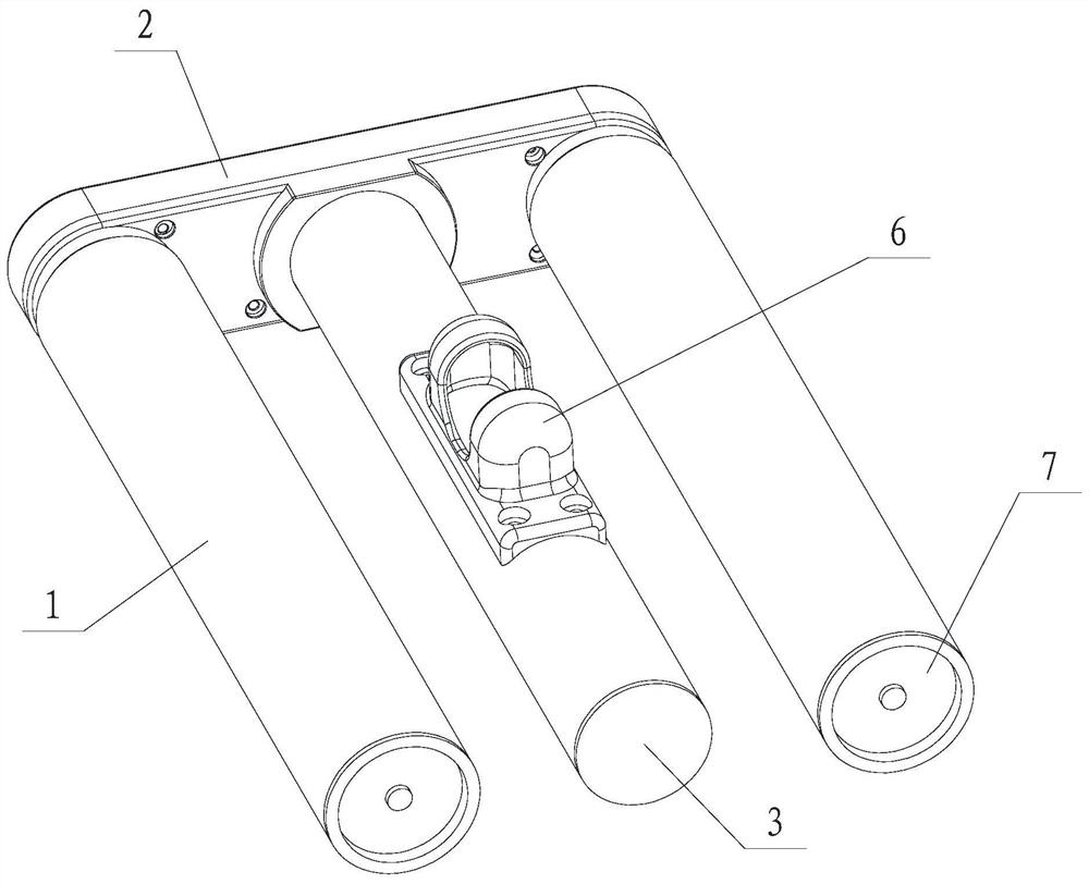
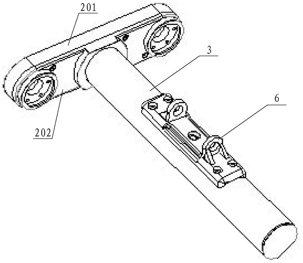
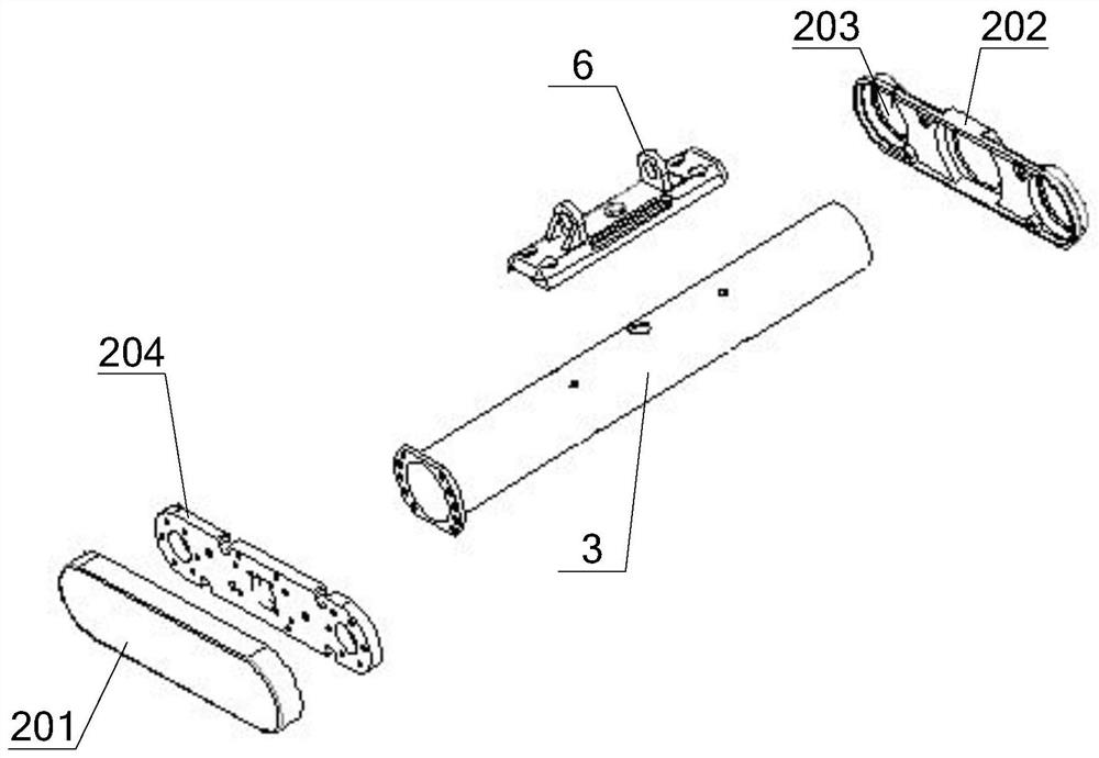
[0040] Such as Figure 1~4 and Figures 10-14 As shown, the fixed plate assembly 2 of the present embodiment includes a fixed plate 204 and an outer cover, the outer cover is divided into an outer cover plate 201 and an inner cover plate 202, and the inner and outer cover plates 202, 201 are connected to form a hollow structure outer cover, and the fixed plate 204 is fixed in the outer cover; three holes 203 are opened on the inner cover 202, the main bracket 3 passes through the hole 203 in the middle, and the other two holes 203 are used for the support components on both sides to pass through. The main bracket 3 and the supporting components on both sides are installed on the fixed plate 204, and the transmission mechanism is housed in the outer cover. A connecting piece 6 is installed on the main bracket 3, and the operating handle of the mopping machine is connected with the connecting piece 6 through a universal joint.

[0041] The transmission mechanism of this embodi...

Embodiment 2

[0047] Such as Figure 1~3 , Figure 5-6 , Figure 12 and Figures 14 to 15 As shown, the difference between this embodiment and Embodiment 1 is that the transmission member 110 of this embodiment is directly connected to the outer drum 102 for transmission, and one end of the inner drum 101 of this embodiment is conical, and the other end is cylindrical. The inside of the part is rotationally connected with the bearing seat 105 through the bearing C108, and the conical part facilitates the insertion of the outer cylinder 102. The difference between the locking member 109 of this embodiment and the first embodiment is that the locking member 109 is located outside the inner drum 101 . In this embodiment, the transmission member 110 is located outside the inner drum 101 and inside the outer drum 102 , and the end of the transmission member 110 away from the fixed plate assembly 2 is evenly distributed with engaging teeth 113 along the circumferential direction. An engaging ...

Embodiment 3

[0049] Such as Figure 1~3 , Figure 7-8 and Figures 10-14 As shown, the difference between this embodiment and Embodiment 1 is that the support assembly of this embodiment includes a bearing seat 105 and a support member 112, and the other end of the bearing seat 105 and the locking member 109 screwed to the end are located on the inner drum 101 Inside the end close to the fixed plate assembly 2 ; the support member 112 is sleeved on the main shaft 104 and keyed to the main shaft 104 , the support member 112 is located on the side of the locking member 109 away from the fixed plate assembly 2 . The inner drum 101 is sleeved on the support member 112 and supported by the support member 112 . The transmission member 110, the inner drum 101, the outer drum 102, the transmission between the transmission member 110 and the inner drum 101, and the transmission between the inner drum 101 and the outer drum 102 in this embodiment are all the same as in the first embodiment, and th...


PUM


Abstract

The invention relates to a ground cleaning device, and in particular, relates to an electric floor mopping machine; a main support is mounted on a fixing plate assembly, roller assemblies are arrangedon two sides of the main support, and a motor is mounted in the main support; each roller assembly comprises an inner roller, an outer roller, a main shaft, a supporting assembly and a transmission part; the supporting assemblies are arranged on the fixing plate assembly, one end of each main shaft is rotationally mounted on the corresponding supporting assembly, the other end of each main shaftis connected with the corresponding transmission part, and the motor is connected with the main shafts in the roller assemblies on the two sides through a transmission mechanism mounted in the fixingplate assembly and drives the main shafts on the two sides to rotate synchronously and reversely. The inner rollers are rotatably sleeved on the supporting assemblies, the outer rollers sleeve the inner rollers, the transmission parts are in linkage with the main shafts and is in transmission with the outer rollers through the inner rollers or in direct connection transmission with the outer rollers, and mop cloth for mopping the floor is wrapped outside the outer rollers. No gap is generated in the middle, so that the covering width of the floor mopping machine is close to the width of the machine during floor mopping, and the floor mopping efficiency is higher and cleaner due to front-back counter-rotating arrangement.

Description

technical field [0001] The invention relates to a floor cleaning device, in particular to an electric floor mopping machine. Background technique [0002] The utility model relates to a mopping robot navigating through a navigation box. A mopping board with a water storage box is installed on the front of the mopping board, and a cleaning cloth is installed under the mopping board. When starting to work, the water in the water storage box continuously seeps into the cleaning cloth to play the role of humidification. Because the water in the water storage box is limited, it will be used up soon; at the same time, the cleaning cloth will also become dirty quickly, resulting in a limited cleaning area. To continue cleaning, it is necessary to manually add water to the water storage box and replace the cleaning cloth; if If the cleaning area is large, the above operations need to be repeated many times, and more navigation boxes need to be arranged, which makes its use more cum...

Claims


Application Information

Patent Timeline
IPC IPC(8): A47L11/282A47L11/40
CPCA47L11/282A47L11/4041A47L11/4069
Inventor 陈博
Owner 陈博
Why Eureka
Try Eureka