Fabricated wall with bottom junction box mounted on outdoor side and construction method of fabricated wall

A prefabricated, outdoor-side technology, used in building structures, walls, buildings, etc., can solve the problem that the location of the junction box cannot meet user requirements, and achieve the effect of reducing manufacturing difficulty, improving production efficiency, and facilitating later maintenance and replacement.

Pending Publication Date: 2020-09-08
BEIJING NEW BUILDING MATERIALS PLC
View PDF0 Cites 0 Cited by
  • Summary
  • Abstract
  • Description
  • Claims
  • Application Information

AI Technical Summary

Problems solved by technology

[0004] The embodiment of the present invention provides a prefabricated wall with a junction bottom box installed on the outdoor side and its construction method, which can simplify the production process of the wall module, improve production efficiency, and solve the problem that the location of the junction bottom box cannot meet the user's requirements question

Method used


Image

  • Fabricated wall with bottom junction box mounted on outdoor side and construction method of fabricated wall
  • Fabricated wall with bottom junction box mounted on outdoor side and construction method of fabricated wall
  • Fabricated wall with bottom junction box mounted on outdoor side and construction method of fabricated wall

Examples


Embodiment 1

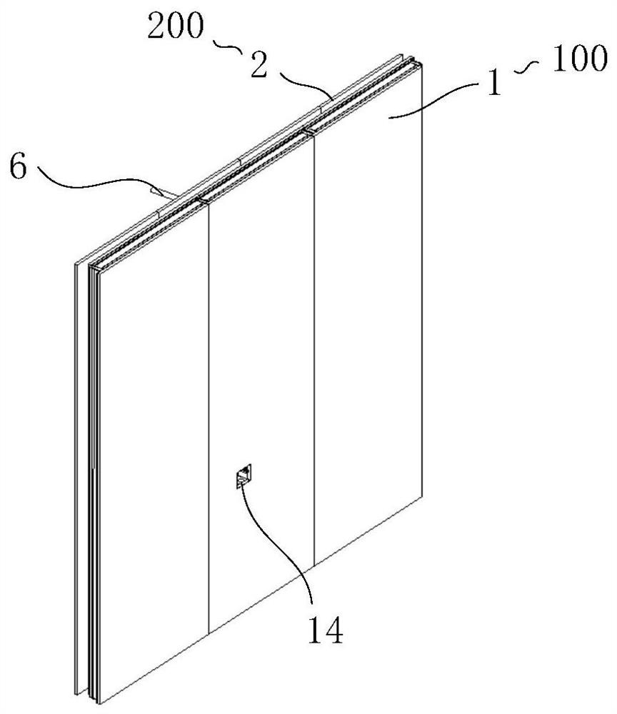
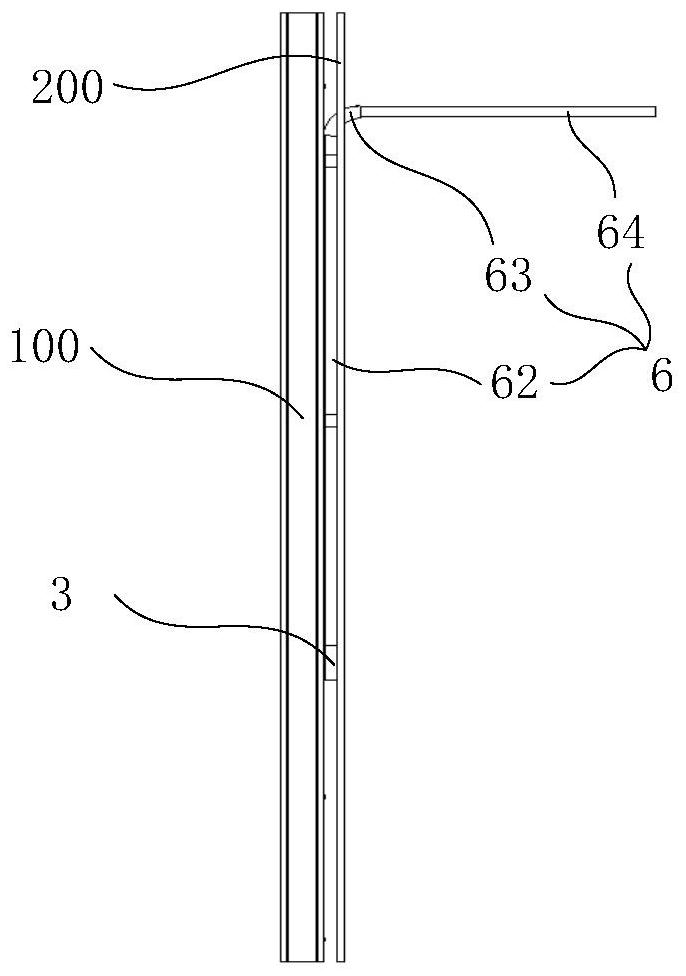
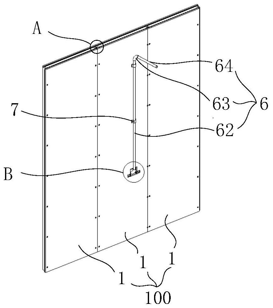
[0065] In some embodiments, refer to Figure 17 , in the prefabricated wall (between the main wall 100 and the wall decoration board 200 ), a large number of line pipes 6 or water pipes are usually arranged to meet the electricity and water requirements of the building itself.

[0066] In some embodiments, refer to Figure 18 , Figure 19 and Figure 20 , the side wall of the decorative wall panel 200 close to the main wall 100 is fixed with an elastic clip 8, the elastic clip 8 has a C-shaped slot 8a on the side close to the main wall 100, and the C-shaped slot 8a is locked with the wire tube 6 Then, the decorative wall panel 200 is fixed on the surface of the main wall 100 . Compared with the fixed structure that cooperates with each other between the decorative wall panel 200 and the main wall 100 , in this embodiment, through the cooperation of the elastic clip 8 and the wire tube 6 , it only needs to be close to the decorative panel 200 . One side of the main wall 100...

Embodiment 2

[0069] In some embodiments, there may be some areas in the prefabricated wall that are not provided with or only have a small number of conduits 6 . In this case, the distribution of conduits 6 is insufficient to provide attachment positions for the elastic clips 8 . At this time, the wire duct 6 only for fixing the decorative wall panel 200 may be installed on the surface of the main wall 100 . However, it will increase the usage of the line pipe 6 and increase the overall construction cost of the prefabricated wall.

[0070] For the above reasons, in some embodiments, refer to Figure 21 , a first clamping structure 9 is provided between the decorative wall panel 200 and the main wall 100, and the first clamping structure 9 includes a buckle 9a and a clamping head 9b. The buckle 9a has a circular groove, and the inner side of the opening of the groove is provided with a clamping flange 93; The outer side of the claw 95 is provided with a clamping protrusion 951 that cooper...

Embodiment 3

[0075] The first clamping structure 9 is fixed point-to-point. When the area of ​​the sub-decorative board 2 is large and a plurality of first clamping structures 9 need to be arranged between the sub-decorative board 2 and the main wall 100, the first clamping structure The positional accuracy of the structure 9 is required to be relatively high, which affects the installation efficiency of the sub-decorative panel 2, which in turn affects the overall construction speed of the prefabricated wall.

[0076] Based on the above reasons, in this embodiment, a second clamping structure 20 is provided between the decorative wall panel 200 and the main wall 100 , and is fixedly connected by the second clamping structure 20 . refer to Figure 25 , the second clamping structure 20 includes a square tube 201, the square tube 201 includes a first tube wall and a second tube wall arranged oppositely, the first tube wall and the surface of the main wall 100 are attached and fixed, along th...


PUM


Abstract

The invention discloses a fabricated wall with a bottom junction box mounted on the outdoor side and a construction method of the fabricated wall, and relates to the technical field of buildings. Theproblem that the position of the bottom junction box cannot meet the requirements of users is solved. The fabricated wall comprises a main wall, a wall decoration plate, the bottom junction box with an opening, corner fasteners, fixing parts and a line pipe, wherein the wall decoration plate is fixed to the surface of the main wall, a mounting hole is formed in the main wall, the bottom junction box is located in the mounting hole, and the opening of the bottom junction box is flush with the outer wall of the main wall; each corner fastener comprises a first wing plate and a second wing platewhich are arranged in an L shape, the first wing plates are closely attached and fixed to the main wall, long strip holes are formed in the second wing plates, and the second wing plates are attachedto the side walls of the bottom junction box; the fixing parts penetrate through the long strip holes to be fixed to the bottom junction box, can slide along the long strip holes, and can compress thesecond wing plates on the side walls of the bottom junction box; and the line pipe is fixed to the inner wall of the main wall, and one end of the line pipe communicates with the bottom junction box.The construction method is used for constructing the wall.

Description

technical field [0001] The invention relates to the technical field of construction, in particular to a prefabricated wall with a junction bottom box installed on the outdoor side and a construction method thereof. Background technique [0002] In the process of building construction, a structural load-bearing frame, such as a steel structure or a poured cement frame structure, is usually constructed first. In the middle of the structural load-bearing frame, an inner partition wall needs to be built according to specific functions. At present, the construction of the wall can be constructed by using light steel profiles and gypsum boards on site, or it can be constructed by splicing wall modules. Due to the use of light steel profiles and gypsum boards for on-site construction, the construction site is messy, and there are too many construction wastes such as scraps and leftovers. The built walls cannot be disassembled, cannot be recycled, and require a large amount of labor...

Claims


Application Information

Patent Timeline
Patent Type & Authority Applications(China)
IPC IPC(8): E04B2/74E04C2/38E04C2/34E04C2/52E04F13/24H02G3/12
CPCE04B2/74E04B2/7407E04B2002/7488E04C2/34E04C2/38E04C2/52E04C2002/3488E04F13/0835E04F13/0858H02G3/123
Inventor 赵永生
Owner BEIJING NEW BUILDING MATERIALS PLC
Why Eureka
Try Eureka