Novel numerical control fan shell structure

A casing structure and fan casing technology, which is applied in mechanical equipment, machines/engines, liquid fuel engines, etc., can solve the problems that the base affects the use of the fan, the difficulty of disassembling the filter, and the inability to change the wind force, etc., to achieve the purpose of expanding the discharge The effect of improving the range, improving the scope of application, and expanding the range of angle adjustment

Active Publication Date: 2020-09-08
安徽庐风风机有限公司
View PDF14 Cites 3 Cited by
  • Summary
  • Abstract
  • Description
  • Claims
  • Application Information

AI Technical Summary

Problems solved by technology

[0003] The purpose of the present invention is to solve the problems in the prior art that the filter screen is difficult to disassemble, the wind force cannot be changed and the adjustment of the base affects the use of the fan, and a new numerically controlled fan shell structure is proposed.

Method used


Image

  • Novel numerical control fan shell structure
  • Novel numerical control fan shell structure
  • Novel numerical control fan shell structure

Examples


Embodiment Construction

[0038] The following will clearly and completely describe the technical solutions in the embodiments of the present invention with reference to the accompanying drawings in the embodiments of the present invention. Obviously, the described embodiments are only some, not all, embodiments of the present invention. Based on the embodiments of the present invention, all other embodiments obtained by persons of ordinary skill in the art without creative efforts fall within the protection scope of the present invention.

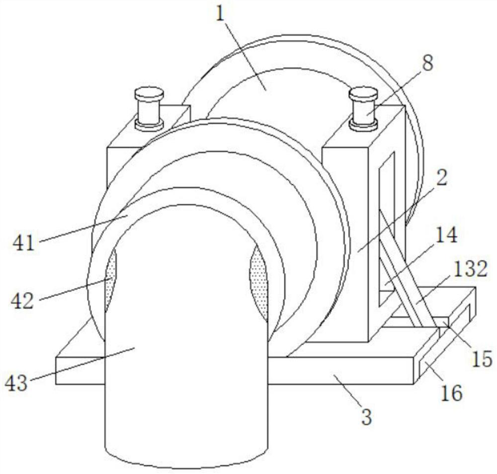
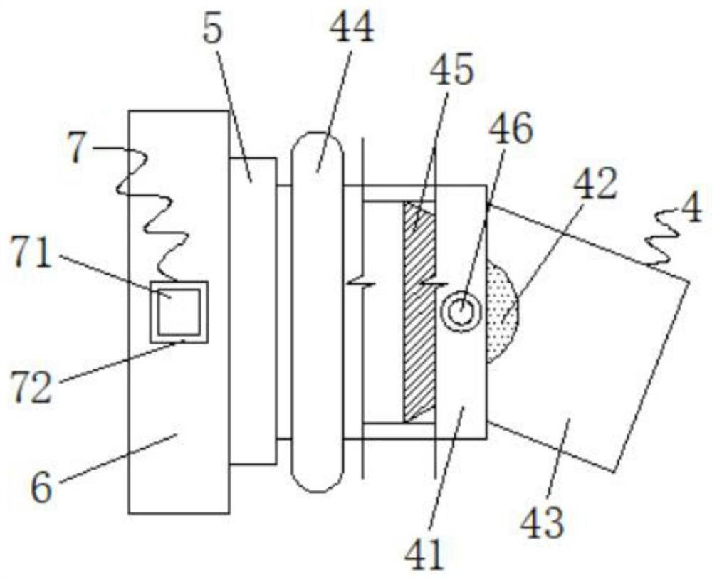
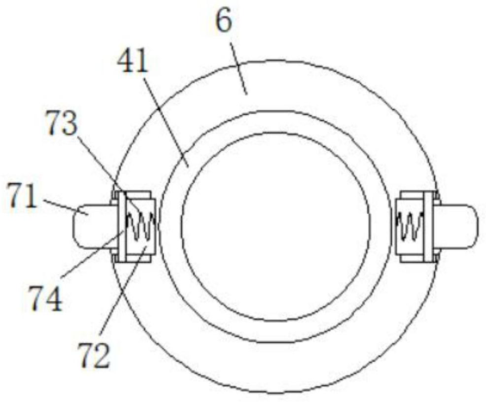
[0039] see Figure 1-7 , the present invention provides a technical solution: a novel numerical control fan casing structure, including a fan casing 1, a casing 2 and a bottom plate 3, the upper surface of the bottom plate 3 is fixedly connected with two casings 2, and the two casings 2 The fan casing 1 is fixedly connected between them, the fan casing 1 is provided with a fixed ring 6, and the left and right sides of the fixed ring 6 are provided with a positionin...


PUM


Abstract

The invention discloses a novel numerical control fan shell structure, and belongs to the technical field of numerical control fans. The structure comprises a fan shell, outer shells and a base plate.The two outer shells are fixedly connected to the upper surface of the base plate. The fan shell is fixedly connected between the two outer shells. A fixing ring is arranged inside the fan shell. Theleft and right sides inside the fixing ring are each provided with a positioning mechanism. The portions, corresponding to the two positioning mechanisms of the outer surface of the fan shell are each provided with a clamping hole. By arranging an air guiding mechanism, a first air guiding tube and a second air guiding tube are arranged inside the air guiding mechanism, the first air guiding tubecan be adjusted inside the second air guiding tube by a certain angle, and therefore smoke can be exhausted at different angles through the first air guiding tube and the second air guiding tube. Dueto the positioning mechanisms, when the air guiding mechanism needs to be used, the positioning mechanisms can be used for disassembling the air guiding mechanism from the fan shell, at the moment, wind power exhausted by the fan shell can be exhausted along the normal track, and the application range of the fan is greatly enlarged.

Description

technical field [0001] The invention belongs to the technical field of numerical control fans, and in particular relates to a novel casing structure of numerical control fans. Background technique [0002] Existing fans have airflow in the same direction as the axis of the fan blades, such as electric fans and air conditioner external fans are fans that operate in axial flow mode. The reason why it is called "axial flow" is because the gas flows parallel to the axis of the fan, Flow fans are usually used in occasions with high flow requirements and low pressure requirements, while CNC fans are connected to a CNC controller on the outside of the fan, and the controller is used to accurately control the wind force and working time of the fan. Compared with traditional fans, By improving its degree of automation, the CNC fan is more convenient to use. The Chinese patent discloses "a shell structure of an enhanced axial fan and an axial fan" (patent number: CN201920599295.7), wh...

Claims


Application Information

Patent Timeline
IPC IPC(8): F04D25/08F04D29/52F04D29/54F04D29/64F04D29/70
CPCF04D25/08F04D29/522F04D29/545F04D29/646F04D29/703
Inventor 傅强杨从贵管照正彭拥军王晓松周玉红徐经存
Owner 安徽庐风风机有限公司
Why Eureka
Try Eureka