Cutting edge detection device

A detection device and cutting edge technology, applied in the field of mechanical processing, can solve problems such as troublesome use, low tool life, equipment damage, etc., and achieve the effects of improving detection efficiency, prolonging service life, and facilitating detection

Pending Publication Date: 2020-09-08
HENAN INST OF ENG
View PDF1 Cites 0 Cited by
  • Summary
  • Abstract
  • Description
  • Claims
  • Application Information

AI Technical Summary

Problems solved by technology

[0002] In the field of mechanical processing, the damage of the tool will not only lead to the scrapping of the workpiece and the damage of the equipment, but also directly affect the precision, efficiency and economic benefits of the machining. In order to reduce the loss caused by the tool damage, many factories often directly follow the average life of the tool Replacing the too

Method used


Image

  • Cutting edge detection device
  • Cutting edge detection device
  • Cutting edge detection device

Examples


Embodiment Construction

[0014] The embodiments of the present invention will be described in further detail below with reference to the accompanying drawings and examples. The following examples are intended to illustrate the present invention, but not to limit the scope of the present invention.

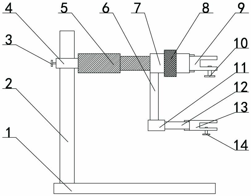
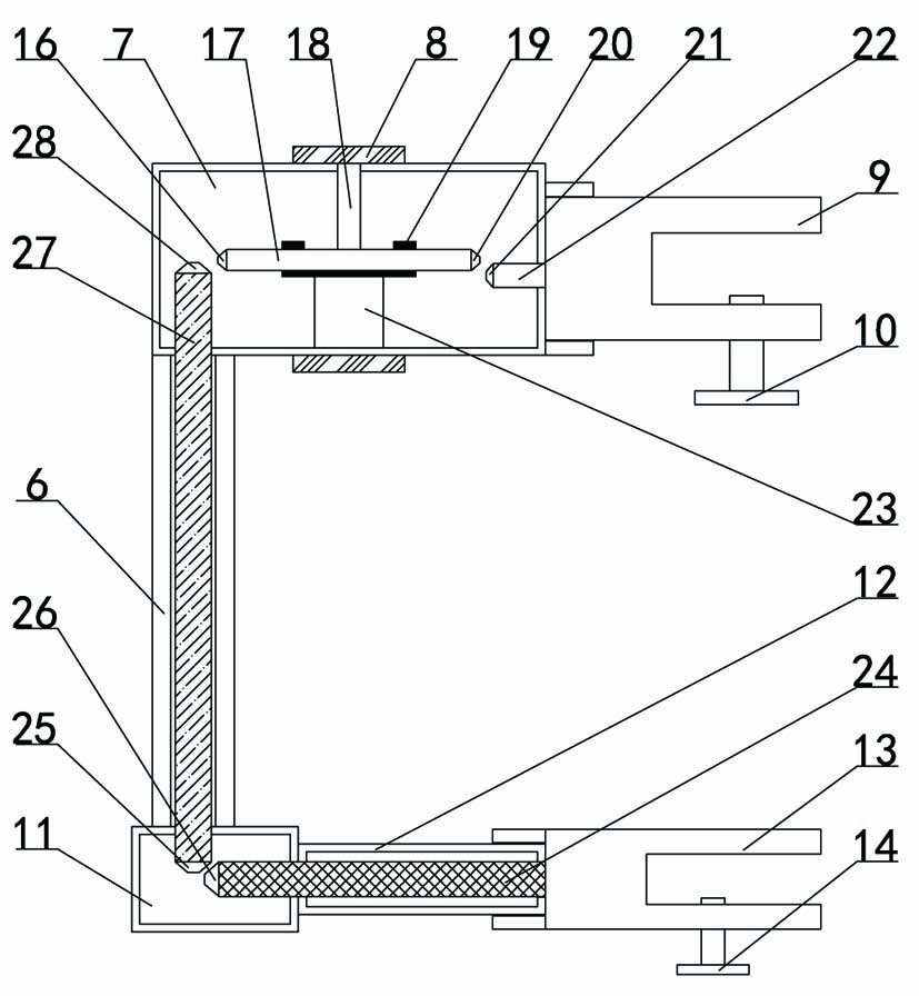
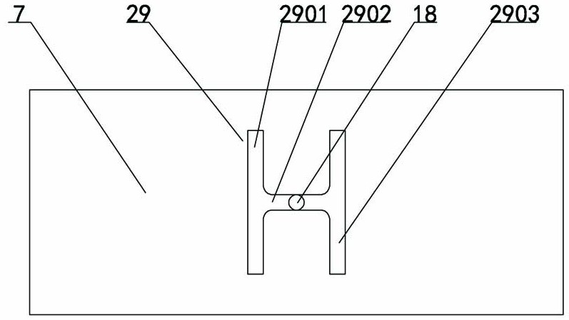
[0015] like Figure 1-4 As shown, a cutting edge detection device includes a base plate 1, a fixing rod 2 is arranged above the left side of the base plate 1, the fixing rod 2 is covered with a sleeve 4, the left side of the sleeve 4 is provided with a first locking bolt 3, and the right side of the sleeve 4 is provided. The telescopic rod 5 is fixed on the side, the right end of the telescopic rod 5 is fixed with the first box body 7, the middle part of the first box body 7 is provided with a rotating ring 8, the inner side of the rotating ring 8 is fixed with a first connecting rod 18, and the first connecting rod 18 is arranged in the first box body In the slot 29 on the 7, the slot 29 is H-shaped, and...


PUM


Abstract

The invention relates to the technical field of machining. The invention particularly relates to a cutting edge detection device. The detection device comprises a bottom plate, a fixed rod is arrangedabove the left side of the bottom plate; a sleeve sleeves the fixed rod, a first locking bolt is arranged in the left of the sleeve; a telescopic rod is fixed in right side of sleeve, a first box isfixed at the right end of the telescopic rod; a rotating ring is arranged in the middle of the first box; a first fixing clamp is fixed at the right end of the first box; a second locking bolt is arranged on the first fixing clamp; a first connecting pipe is fixed in the lower side of the first box; a second box is fixed at the lower end of the first connecting pipe; a second connecting pipe is fixed in the right of the second box; a second fixing clamp is fixed at the right end of the second connecting pipe; and a third locking nut is arranged on the second fixing clamp. When the cutting edgeneeds to be detected, an observation device is fixed to the first fixing clamp, the cutting edge is fixed to the second fixing clamp, the observation device and the cutting edge are adjusted throughthe rotating ring, the situation of the cutting edge can be clearly seen, and the cutting edge can be conveniently detected.

Description


Claims


Application Information

Patent Timeline
Owner HENAN INST OF ENG
Why Eureka
Try Eureka