
Camera module and electronic equipment

A camera module and module technology, applied in the direction of TV, electrical components, color TV, etc., can solve the problem of poor imaging quality of the camera module, and achieve the effect of reducing distortion and reducing the photosensitive area

Active Publication Date: 2020-09-08
VIVO MOBILE COMM CO LTD
View PDF6 Cites 3 Cited by
  • Summary
  • Abstract
  • Description
  • Claims
  • Application Information

AI Technical Summary

Problems solved by technology

[0005] The present application discloses a camera module and electronic equipment, which can solve the problem of poor imaging quality in the current camera modules of electronic equipment

Method used


Image

  • Camera module and electronic equipment
  • Camera module and electronic equipment
  • Camera module and electronic equipment

Examples


Embodiment Construction

[0029] The following will clearly and completely describe the technical solutions in the embodiments of the present application with reference to the drawings in the embodiments of the present application. Obviously, the described embodiments are part of the embodiments of the present application, not all of them. Based on the embodiments in this application, all other embodiments obtained by persons of ordinary skill in the art without making creative efforts belong to the scope of protection of this application.

[0030] The terms "first", "second" and the like in the specification and claims of the present application are used to distinguish similar objects, and are not used to describe a specific sequence or sequence. It is to be understood that the data so used are interchangeable under appropriate circumstances such that the embodiments of the application can be practiced in sequences other than those illustrated or described herein. In addition, "and / or" in the specific...


PUM


Abstract

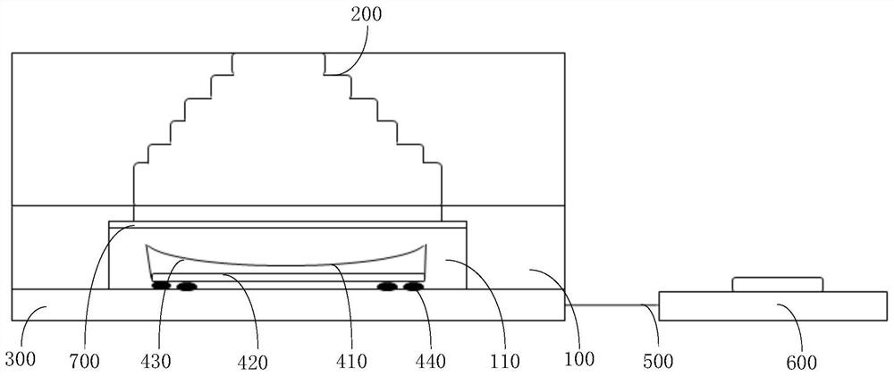
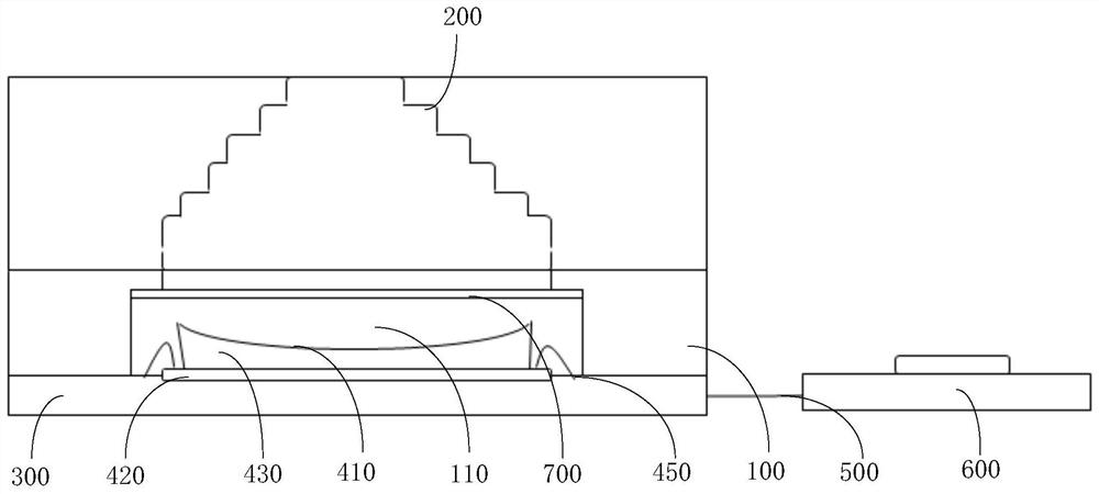
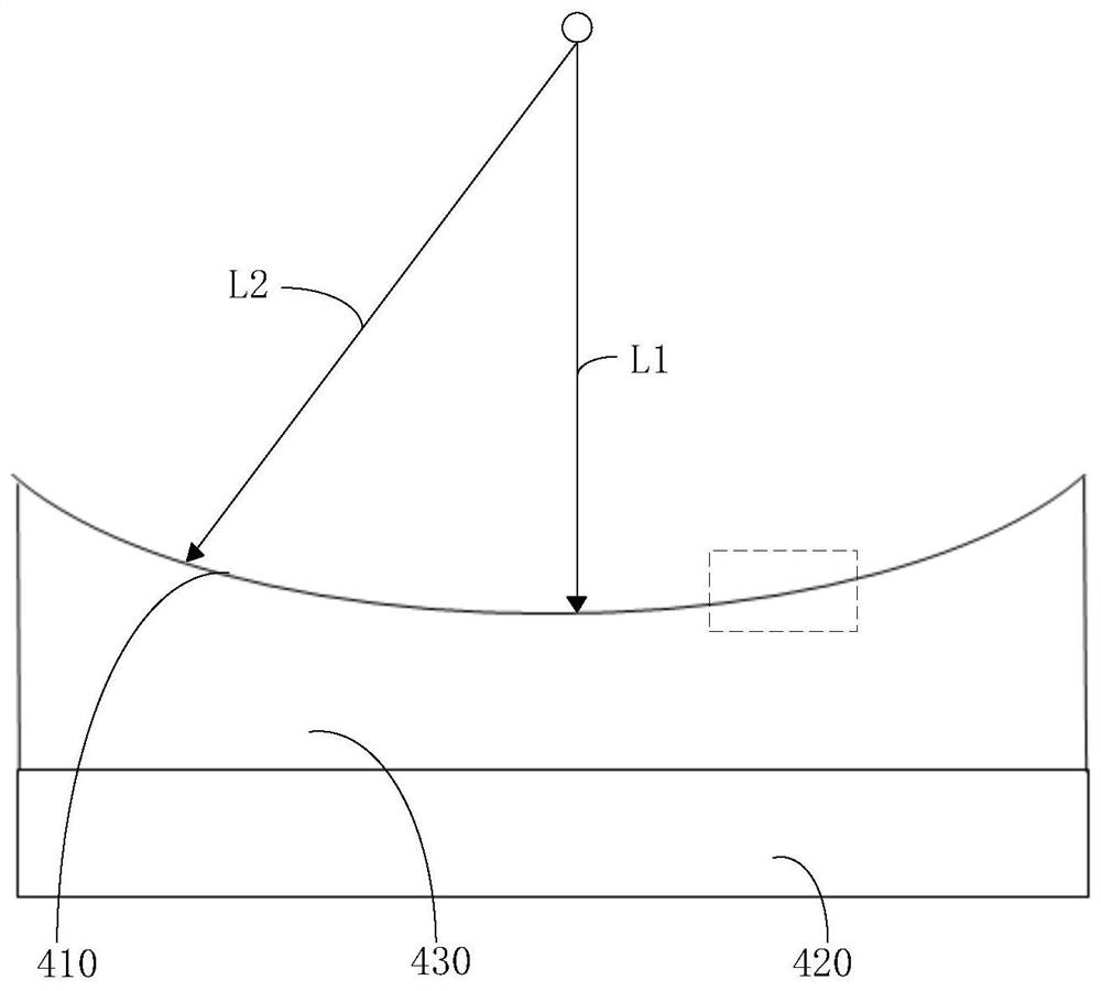
The invention discloses a camera module. The camera module comprises a bracket (100); a lens (200), wherein the lens (200) is arranged on the bracket (100); a substrate (300), wherein the substrate (300) is connected with the bracket (100); and a photosensitive chip module (400), wherein the photosensitive chip module (400) is arranged on the substrate (300), the photosensitive chip module (400) is electrically connected with the substrate (300), the photosensitive chip module (400) and the lens (200) are oppositely arranged, the photosensitive chip module (400) is provided with a light receiving surface (410) facing the lens (200), the light receiving surface (410) is a concave surface, and the light receiving surface (410) is formed by splicing a plurality of bulges (411) distributed inan array. The invention further discloses electronic equipment. According to the scheme, the problem of poor imaging quality of the camera module of the existing electronic equipment can be solved.

Description

technical field [0001] The present application relates to the technical field of communication equipment, in particular to a camera module and electronic equipment. Background technique [0002] With the rapid development of electronic equipment, the application of electronic equipment is becoming more and more extensive. Electronic equipment such as mobile phones and tablet computers play more and more roles in people's work, life, and entertainment. [0003] At present, users have higher and higher requirements for photographing effects of electronic devices. Usually, since natural light is mixed with various lights, during the shooting process of the camera module of electronic equipment, after the light of different wavelengths is refracted by the lens of the camera module, due to the different wavelengths of different light rays, different light rays are reflected on the lens. The refractive index will also be different. [0004] Therefore, in order to collimate and c...

Claims


Application Information

Patent Timeline
Patent Type & Authority Applications(China)
IPC IPC(8): H04N5/225
CPCH04N23/54H04N23/57H04N23/55H04N23/50H01L27/14627
Inventor 徐波彭士玮高峰
Owner VIVO MOBILE COMM CO LTD
Learn More