
Weak light detection method

A detection method and low-light technology, which is applied in the field of low-light detection, can solve the problems of large photosensitive area on the photosensitive surface, high production success, and large volume of photoelectric sensors, and achieve the goals of reducing the photosensitive area, saving detection costs, and accurate light response Effect

Inactive Publication Date: 2020-05-15
PUSU OPTOELECTRONICS TECH SUZHOU CO LTD
View PDF3 Cites 0 Cited by
  • Summary
  • Abstract
  • Description
  • Claims
  • Application Information

AI Technical Summary

Problems solved by technology

Since some photogenerated charges will inevitably be lost in the process of photoelectric conversion, that is, the detection limit of the sensor is numerically greater than the sensitivity value, so the sensor cannot detect weak light signals below the detection limit.
Moreover, the photosensitive surface of the currently used photoelectric sensor has a large photosensitive area, resulting in a large volume of the photoelectric sensor, and a correspondingly high production success.
In addition, since the light to be measured may be light of different wavelength bands, it will affect the detection accuracy

Method used


Image

  • Weak light detection method
  • Weak light detection method

Examples


Embodiment Construction

[0030] In the following, the present invention will be further described in conjunction with specific embodiments. It should be noted that, on the premise of not conflicting, the technical features described below can be combined arbitrarily to form new embodiments.

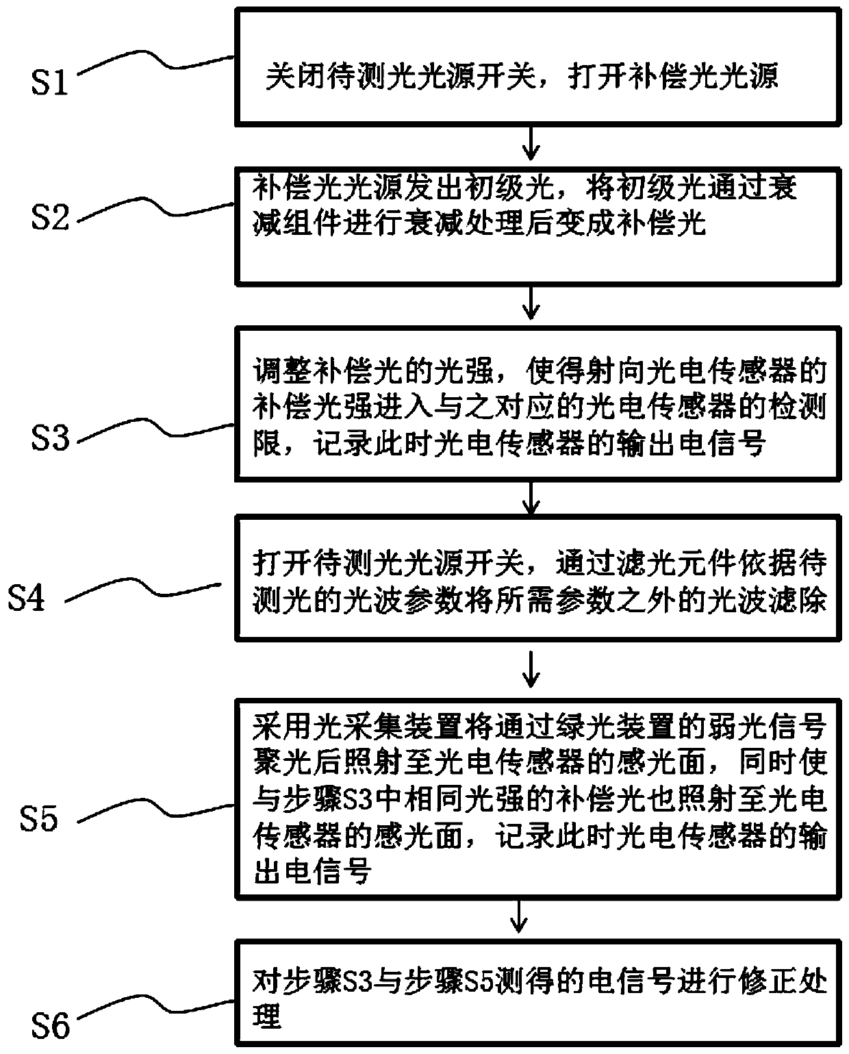
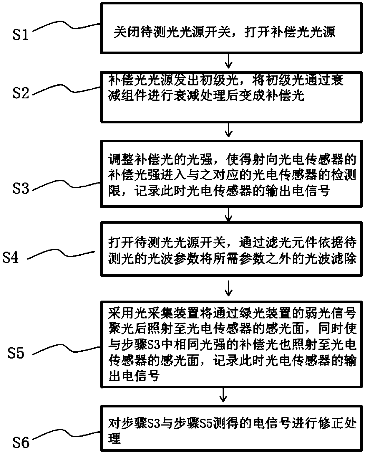
[0031] A low-light detection method, characterized in that, comprising the following steps:

[0032] S1. Turn off the switch of the light source to be tested, and turn on the compensation light source;

[0033] The on and off of the light source to be tested is controlled by a switch, and the switch includes an electronic switch or a mechanical switch. Generally, for molecular absorption spectroscopy, laser Raman spectroscopy, fluorescence excitation spectroscopy and other detection application scenarios where the main light source can be immediately started and stopped to irradiate the sample, the electronic switch is preferred, that is, the main instrument of the instrument is shut down through the control syst...


PUM


Abstract

The invention provides a weak light detection method which comprises the following steps of S1, turning off a switch of a light source to be detected, and turning on a compensation light source; S2, enabling the compensation light source to emit primary light, and attenuating the primary light through an attenuation assembly to form the compensation light; S3, adjusting the light intensity of thecompensation light, enabling the compensation light intensity emitted to the photoelectric sensor to enter the detection limit of a corresponding photoelectric sensor, and recording an output electricsignal of the photoelectric sensor at the moment; S4, turning on the switch of the light source to be detected, and filtering out light waves except the required parameters through a light filteringelement according to the light wave parameters of the to-be-detected light; S5, condensing the weak light signal passing through the light filtering device by adopting a light collecting device, irradiating the condensed weak light signal to the light sensing surface of the photoelectric sensor, irradiating the compensation light with the same light intensity as the compensation light in the stepS3 to the light sensing surface of the photoelectric sensor, and recording an output electric signal of the photoelectric sensor at the moment; S6, correcting the electric signals measured in the stepS3 and the step S5. According to the method, the weak light detection capability of the photoelectric sensor is improved.

Description

technical field [0001] The invention relates to the field of weak light detection, in particular to a weak light detection method. Background technique [0002] There are many demands in various fields for the detection of weak light signals. For this reason, many new photoelectric sensors have been developed, such as photovoltaic detectors, photoconductive detectors, thermopile detectors, photodiodes, photodiode arrays, CCD image sensors, CMOS image sensors, NMOS image sensors, and InGaAs image sensors, Its ability to detect weak light mainly depends on the two parameters of detection limit and sensitivity. Since some photogenerated charges will inevitably be lost in the process of photoelectric conversion, the detection limit is numerically greater than the value of sensitivity. For example, a light The detection limit of the sensor for light energy is 50nJ, and the sensitivity is 1nJ, which means that the sensor cannot detect normally when the light energy is lower than ...

Claims


Application Information

Patent Timeline
Patent Type & Authority Applications(China)
IPC IPC(8): G01J1/04G01J1/42
CPCG01J1/0407G01J1/42
Inventor 冯旭东赵振英
Owner PUSU OPTOELECTRONICS TECH SUZHOU CO LTD
Learn More