
Unmanned aerial vehicle control method for target continuous observation

A control method and unmanned aerial vehicle technology, applied in the direction of attitude control, non-electric variable control, control/adjustment system, etc., can solve the problems of difficult unmanned aerial vehicle attitude control, large discipline coupling, and prone to crash accidents, etc., to achieve The guidance method is simple and feasible, and the effect of the algorithm calculation is small

Active Publication Date: 2020-09-11
BEIJING RES INST OF MECHANICAL & ELECTRICAL TECH
View PDF5 Cites 0 Cited by
  • Summary
  • Abstract
  • Description
  • Claims
  • Application Information

AI Technical Summary

Problems solved by technology

However, the UAV company needs to open up the control authority and make substantial changes to the existing flight control program; due to delay considerations, only the on-board control method can be adopted, and ground control cannot be used; the coupling of disciplines is large, and it is difficult for UAV companies to carry out instructions. Inspection, it is prone to crash accidents; after the drone fails, it is difficult to divide the responsibility for the accident
[0006] To sum up, in the flight test for passive detection, when the detection equipment finds the target, it is necessary to adjust the attitude of the drone to align the detection equipment with the target for continuous observation. However, due to the fixed command input form of the drone ( are in the form of waypoints), so it is difficult to directly control the attitude of the UAV

Method used


Image

  • Unmanned aerial vehicle control method for target continuous observation
  • Unmanned aerial vehicle control method for target continuous observation
  • Unmanned aerial vehicle control method for target continuous observation

Examples


Embodiment Construction

[0038] Specific embodiments of the present invention will be described in detail below. In the following description, for purposes of explanation and not limitation, specific details are set forth in order to provide a thorough understanding of the invention. It will be apparent, however, to one skilled in the art that the present invention may be practiced in other embodiments that depart from these specific details.

[0039] It should be noted here that, in order to avoid obscuring the present invention due to unnecessary details, only the device structure and / or processing steps closely related to the solution according to the present invention are shown in the drawings, and the steps related to the present invention are omitted. Invent other details that don't really matter.

[0040] In the present invention, the roughly scattered area of ​​the target is known (the area where the target may exist is guaranteed by the rough target indication accuracy of the passive detecti...


PUM


Abstract

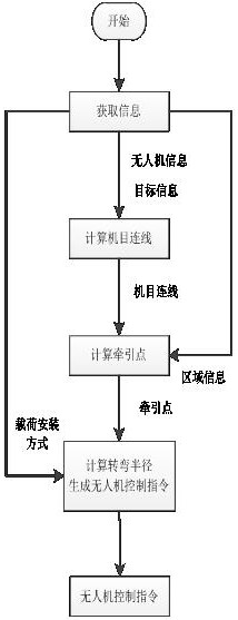
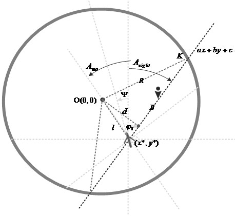
The invention provides an unmanned aerial vehicle control method for target continuous observation. The method comprises the following steps: unmanned aerial vehicle, passive detection equipment and target indication information are acquired, and the position of an unmanned aerial vehicle is calculated; an unmanned aerial vehicle and target connection line is calculated; intersection points of theunmanned aerial vehicle and target connection line and the edge of a target scattering area are calculated, and the intersection points in the unmanned aerial vehicle sight direction are taken as traction points; according to the placement position of passive detection equipment on the unmanned aerial vehicle, the fly-around radius is determined, and an unmanned aerial vehicle control instructionis generated. The method is simple and feasible, the algorithm calculation amount is small, the unmanned aerial vehicle control instruction of fly-around center + fly-around radius is generated, theinput forms of most of unmanned aerial vehicle companies in the existing market are met, the unmanned aerial vehicle companies do not need to greatly change the flight control program, and the verification requirement of passive guidance is met.

Description

technical field [0001] The invention belongs to the technical field of unmanned aerial vehicle control, and in particular relates to an unmanned aerial vehicle control method for continuous target observation. Background technique [0002] In the research of passive guidance technology, the verification of passive guidance process is usually carried out by means of helicopter flying and hardware-in-the-loop simulation. With the development of UAV technology and the improvement of equipment miniaturization capabilities, UAV flying tests can be used to verify passive detection equipment and guidance laws. This test technology is more effective in the inspection of complex guidance processes. Advantages are particularly important in the verification of cooperative guidance algorithms. [0003] During the drone flight test, the test is usually carried out in cooperation with the drone company. Before the test, the passive detection equipment needs to be installed on the UAV, a...

Claims


Application Information

Patent Timeline
IPC IPC(8): G05D1/08G05D1/10
CPCG05D1/0808G05D1/101
Inventor 侯冀川李红春尹志德
Owner BEIJING RES INST OF MECHANICAL & ELECTRICAL TECH
Learn More