Pain tester device for anesthesia department

An analgesia instrument and technology of anesthesiology department, applied in the field of medical devices, can solve problems such as the influence of pain measurement results by electrical stimulation of analgesia instrument

Pending Publication Date: 2020-09-15
温显让
View PDF7 Cites 1 Cited by
  • Summary
  • Abstract
  • Description
  • Claims
  • Application Information

AI Technical Summary

Problems solved by technology

[0004] The purpose of the present invention is to solve the shortcomings in the prior art that the analgesia instrument fixes the conductive structure by placing clips on the user's body, and the stimulation of the clips will affect the electrical stimulation pain measurement results of the analgesia instrument, and proposes An analgesia device for anesthesiology

Method used


Image

  • Pain tester device for anesthesia department
  • Pain tester device for anesthesia department
  • Pain tester device for anesthesia department

Examples


Embodiment 1

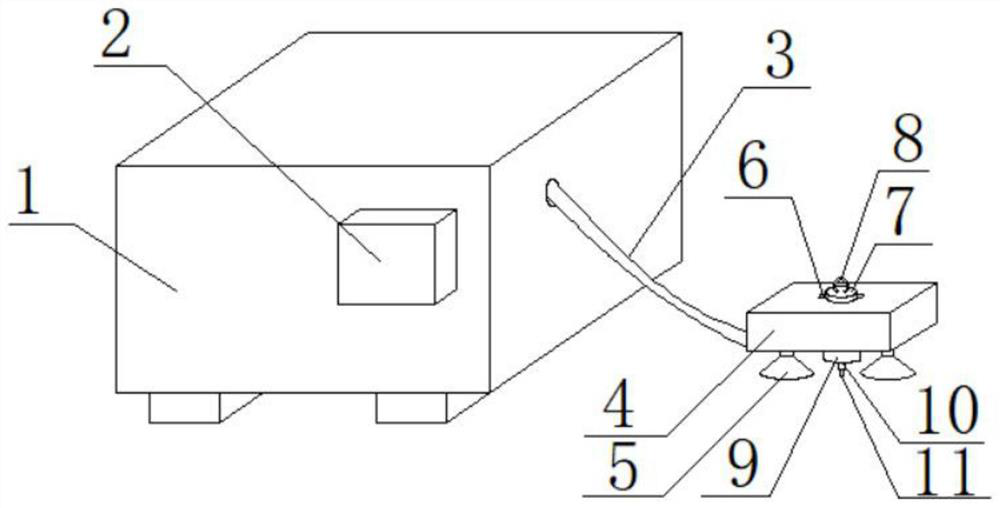
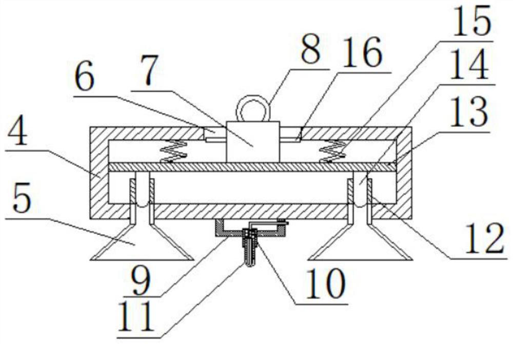
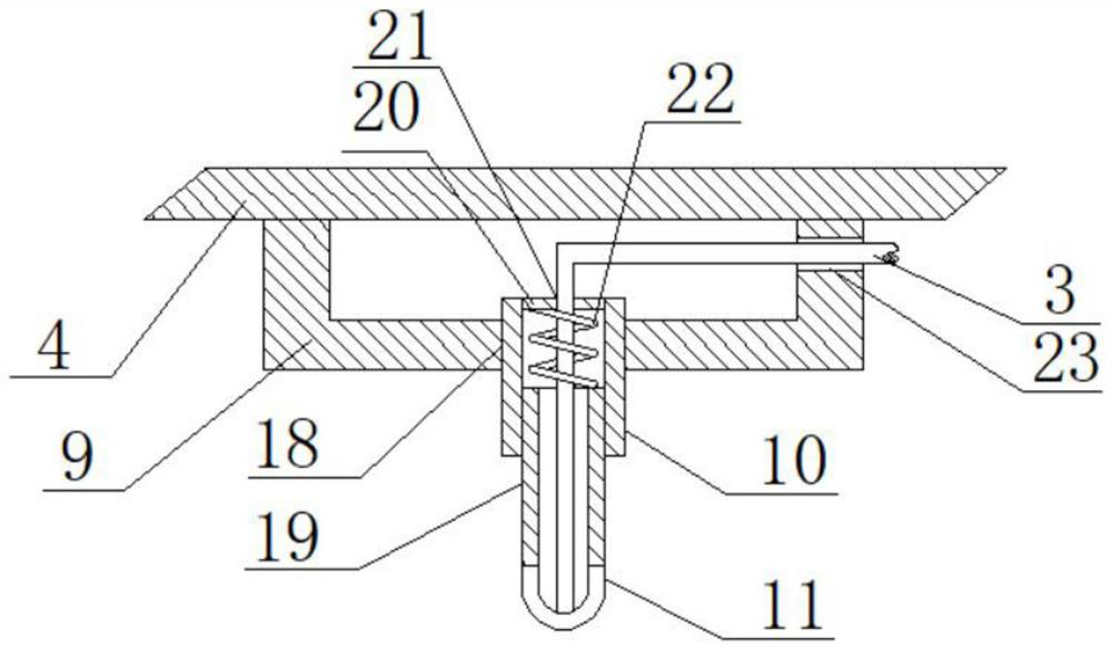
[0028] refer to Figure 1-5 , an analgesia device for anesthesiology, comprising a controller 1, a control panel 2 is arranged on the controller 1, one end of a wire 3 is connected to the controller 1, the controller 1 can be connected to an external power supply, and the current of the controller 1 can be Output to the wire 3, the control panel 2 adjusts the current and voltage output to the wire 3 by controlling the internal components of the controller 1, the other end of the wire 3 is connected to the needle base 9, and the needle base 9 is fixedly installed with the fixing seat 4 , the bottom of the fixing seat 4 is provided with two first through holes, the suction cup 5 is fixedly installed in the two first through holes, the material of the suction cup 5 is relatively hard, and the bottom of the needle base 9 is provided with a third through hole 18, the second A needle tube 10 is fixedly installed in the three-way hole 18, a slide tube 19 is slidably installed on the ...

Embodiment 2

[0038] refer to Figure 1-5, an analgesia device for anesthesiology, comprising a controller 1, a control panel 2 is arranged on the controller 1, one end of a wire 3 is connected to the controller 1, the controller 1 can be connected to an external power supply, and the current of the controller 1 can be Output to the wire 3, the control panel 2 adjusts the current and voltage output to the wire 3 by controlling the internal components of the controller 1, the other end of the wire 3 is connected to the needle base 9, and the needle base 9 is welded with the fixing seat 4, The bottom of the fixing seat 4 is provided with two first through holes, and a suction cup 5 is welded in the two first through holes, and the material of the suction cup 5 is relatively hard. A needle tube 10 is installed in the hole 18. A slide tube 19 is slidably installed on the needle tube 10. A needle head 11 is welded on the slide tube 19. The needle head 11 matches the wire 3. The needle head 11 is...


PUM


Abstract

The invention belongs to the technical field of medical instruments, and particularly relates to a pain tester device for the anesthesia department. Aiming to solve the problems that an existing paintester fixes a conductive structure by placing a clamp on the body of a user, and stimulation of the clamp may affect an electrical stimulation pain testing result of the pain tester, now the following scheme is provided, the pain tester device for the anesthesia department comprises a controller, wherein a control panel is arranged on the controller, one end of a wire is connected to the controller, a needle base is connected to the other end of the wire, a fixing base is fixedly installed on the needle base, two first through holes are formed in the bottom of the fixing base, and suction cups are fixedly installed in the two first through holes. According to the paint tester device, a needle head is used for conducting electricity and can tightly abut against the surface of the body of auser through elastic force of the second spring; and the fixing base is fixed through the suction cups, the suction cups increase adsorption force through a sliding plate and other structures, the sliding plate is controlled through a rotating column, the rotating column can be fixed through a sliding groove, and the pain tester device can be operated by only needing to operate the rotating column in a whole process.

Description

technical field [0001] The invention relates to the technical field of medical devices, in particular to an analgesia device for anesthesiology. Background technique [0002] Pain measuring instrument is an instrument that can apply certain stimulation to the human body. The common stimulation method used in pain measuring instrument is to apply low-voltage current to the human body, and stimulate the nerves of the human body through the current, so as to make the human body feel pain. Its working principle is similar to Childbirth experience instrument, but the pain tester is mainly used to test whether the pain reflex of the user is normal after being anesthetized by drugs. Therefore, the pain tester usually has a small electric shock area, which is convenient for detecting the nerves of different positions of the user. [0003] The main function of the existing pain measuring instrument is to contact and fix the conductive structure with the human body, and then energize ...

Claims


Application Information

Patent Timeline
Patent Type & Authority Applications(China)
IPC IPC(8): A61B5/00
CPCA61B5/4824A61B5/4821A61B5/0048
Inventor 温显让
Owner 温显让
Why Eureka
Try Eureka