
Thermostatic bath

A constant temperature tank and tank bottom technology, applied in the field of constant temperature tanks, can solve problems such as backwardness, achieve the effects of increased heating and cooling speed, reduced external insulation layer, and small space occupation

Active Publication Date: 2020-09-15
BEIJING CONST INSTR TECH INC
View PDF8 Cites 3 Cited by
  • Summary
  • Abstract
  • Description
  • Claims
  • Application Information

AI Technical Summary

Problems solved by technology

However, due to technical limitations, small and portable constant temperature baths often lag behind traditional large-scale constant temperature baths in terms of temperature field stability and temperature field uniformity.

Method used


Image

  • Thermostatic bath
  • Thermostatic bath
  • Thermostatic bath

Examples


Embodiment 1

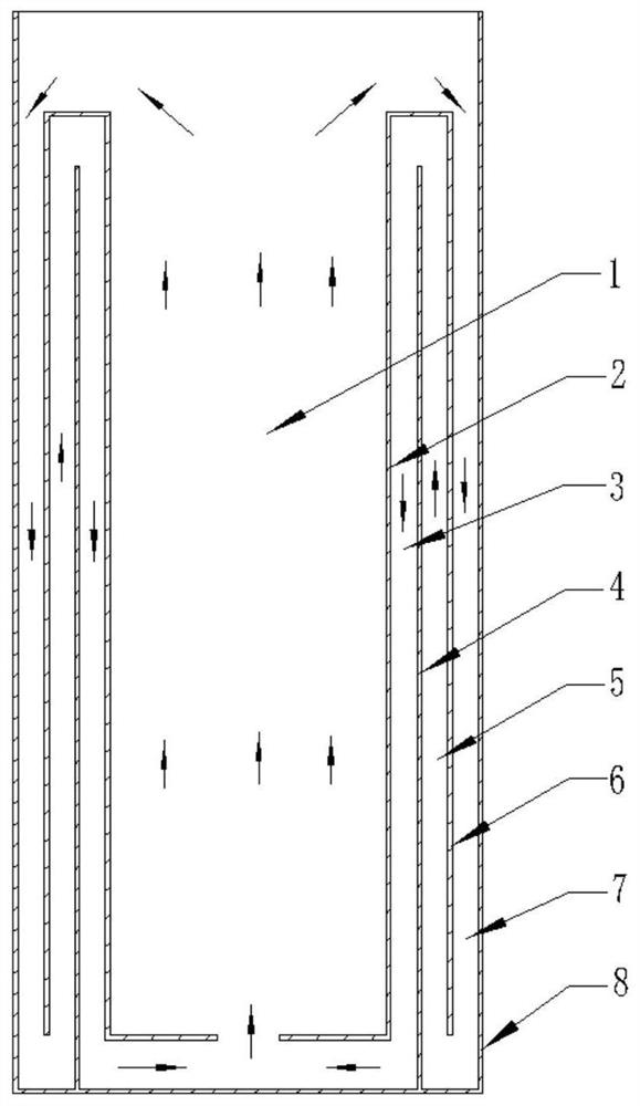
[0035] Such asfigure 1 As shown in , a schematic cross-sectional structure diagram of the constant temperature bath provided in this embodiment is shown. It can be seen that the thermostatic tank provided in this embodiment includes an annular outer casing 8 and a three-layer annular baffle disposed inside the annular outer casing 8, wherein the annular outer casing 8 includes an annular groove wall located at the circumference and a groove bottom located at the bottom , the three layers of baffles are the first layer of annular baffles 6 , the second layer of annular baffles 4 and the third layer of annular baffles 2 from outside to inside. Wherein the annular space formed between the first layer of annular baffle 6 and the annular groove wall of the annular outer shell 8 is the first flow insulation layer 7; the second layer of annular baffle 4 and the first layer of annular baffle 6 formed The annular space is the second flow insulation layer 5; the annular space formed bet...

Embodiment 2

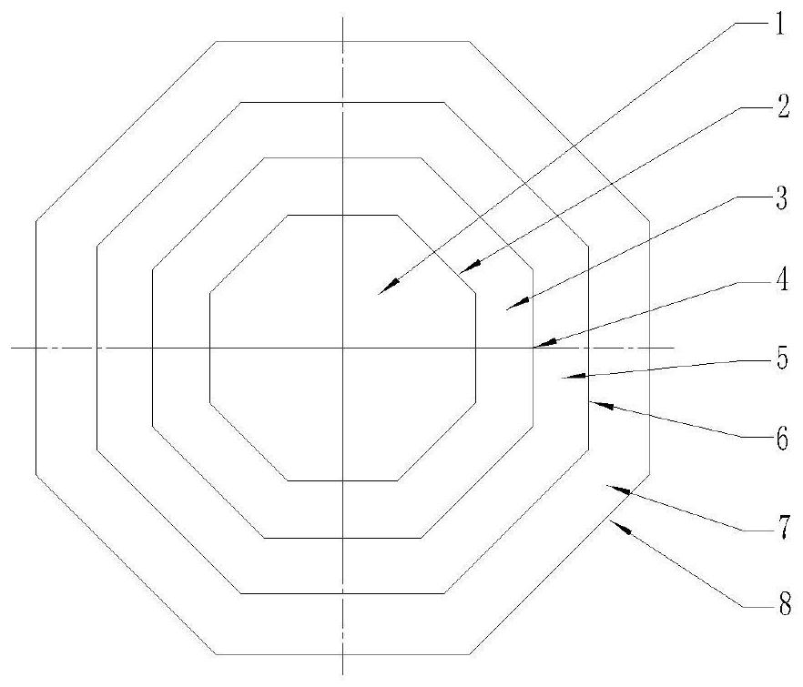
[0040] Such as figure 2 As shown in FIG. 1 , it shows a schematic top view of the thermostatic bath provided in this embodiment. It differs from the thermostatic bath provided in Example 1 only in that the annular outer shell of the thermostatic bath provided by this embodiment is a polygonal columnar outer shell (that is, the top view of the structure surrounded by the outer shell is polygonal), and the annular baffle is also polygonal. The columnar baffle (that is, the structure enclosed by the baffle is polygonal in plan view), wherein the polygon is, for example, an equilateral polygon or a non-equilateral polygon. The polygonal outer casing and the polygonal baffle plate of the constant temperature bath provided in this embodiment are all regular hexagons, and those skilled in the art should understand that they can also be regular triangles, regular quadrilaterals, regular pentagons, non-equilateral triangles, Non-equilateral quadrilaterals, non-equilateral pentagons, ...

Embodiment 3

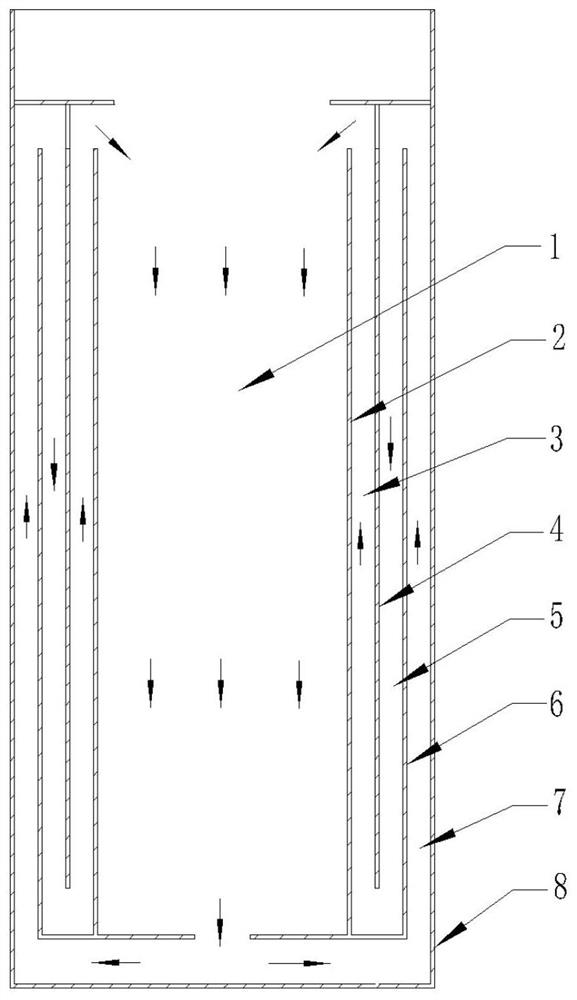
[0042] Such as image 3 As shown in , a schematic cross-sectional structure diagram of the constant temperature bath provided in this embodiment is shown. The difference between the thermostatic bath provided in this embodiment and the thermostatic bath provided in Embodiment 1 is that: the bottom of the first layer of annular baffle 6 and the bottom of the third layer of annular baffle 2 are sealed and connected with the bottom of the annular outer casing 8 All are provided with gaps, which allow the liquid in the tank to enter the first flow insulation layer 7 from the central constant temperature zone 1 . The top of the second layer of annular baffle 4 is sealingly connected with the groove wall of the annular outer shell 8, and a gap is provided between the sealing connection and the top of the first layer of annular baffle 6, which allows the tank liquid to flow from the first The fluid insulation layer 7 enters into the second fluid insulation layer 5 . A gap is also s...


PUM


Abstract

The invention discloses a thermostatic bath, and belongs to the field of temperature measurement and detection and the field of environmental experiments. The thermostatic bath comprises an annular outer shell and a plurality of layers of annular baffles arranged in the annular outer shell, a central constant-temperature area and a plurality of flowing heat preservation layers in the constant-temperature tank are jointly formed, a liquid in a bath body can circularly flow in the flowing heat preservation layers and the central constant-temperature area, and heat preservation and mixing of theliquid in the bath body can be achieved, so the stability and uniformity indexes of a temperature field of the central constant-temperature area are greatly improved, the size of the bath body can begreatly reduced, and the bath is light in weight, small in occupied space and convenient to move and carry.

Description

technical field [0001] The invention belongs to the field of temperature measurement and detection and the field of environmental experiments, and in particular relates to a constant temperature bath. Background technique [0002] The constant temperature bath is suitable for occasions that need to maintain stable low temperature, normal temperature and high temperature conditions, especially in the field of temperature measurement and environmental experiments, which puts forward very high requirements for the stability and uniformity of the constant temperature field. In order to meet the above-mentioned stability and uniformity requirements of the temperature field, the traditional constant temperature bath often designs the tank volume very large, which has two advantages. First, the volume of liquid contained is large and the heat capacity is also large. The influence of external thermal disturbance on the temperature of the bath liquid with large heat capacity is great...

Claims


Application Information

Patent Timeline
IPC IPC(8): B01L7/00
CPCB01L7/00
Inventor 陈高飞赵士春
Owner BEIJING CONST INSTR TECH INC
Features
  • Generate Ideas
  • Intellectual Property
  • Life Sciences
  • Materials
  • Tech Scout
  • Unparalleled Data Quality
  • Higher Quality Content
  • 60% Fewer Hallucinations
Learn More