Eureka AIR delivers breakthrough ideas for toughest innovation challenges, trusted by R&D personnel around the world.

Three-degree-of-freedom bionic neck movement mechanism

A motion mechanism and degree-of-freedom technology, applied in manipulators, program-controlled manipulators, manufacturing tools, etc., can solve the problems of low degree of bionics, insufficient flexibility and coordination of three degrees of freedom, inflexible operation and use, etc. Flexible, highly bionic effects

Pending Publication Date: 2020-09-15
GUANGDONG UNIV OF TECH
View PDF1 Cites 4 Cited by
  • Summary
  • Abstract
  • Description
  • Claims
  • Application Information

AI Technical Summary

Problems solved by technology

[0004] The present invention overcomes the above-mentioned background technology by changing the length of each support to realize the change of the angle to complete the tilting, pitching and yaw movements; the degree of bionics is still not high in operation, and the three degrees of freedom are insufficient in compliance and coordination. To solve the problem of insufficient flexibility in operation and use, a three-degree-of-freedom bionic neck movement mechanism is provided

Method used


Image

  • Three-degree-of-freedom bionic neck movement mechanism
  • Three-degree-of-freedom bionic neck movement mechanism
  • Three-degree-of-freedom bionic neck movement mechanism

Examples


Embodiment 1

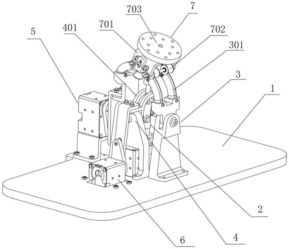
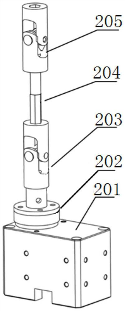
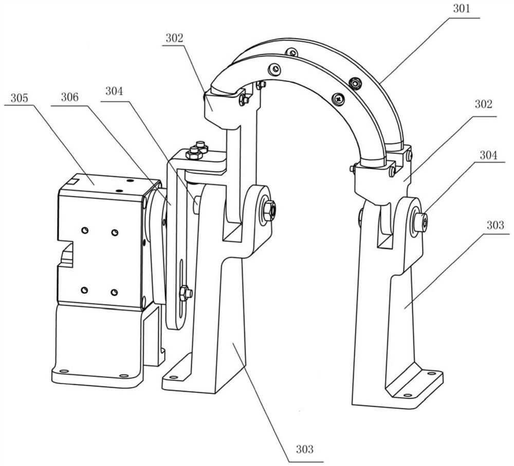
[0024] Such as figure 1 As shown, it is a three-degree-of-freedom bionic neck movement mechanism, which includes a base 1 and a twisting mechanism 2, a pitching mechanism 4, a side swing mechanism 3 and a connecting slider 7, which include a support 701, the roller 702 and the head and neck connector 703, the roller 702 is arranged at one end of the support 701, and one end of the head and neck connector 703 is movably installed on the other end of the support 701, and the side swing mechanism 3 includes a pitch track used in conjunction with the roller 702 301 and the side swing assembly that is located on the base 1 and can drive the swing track 301 to swing. The connecting slider 7 is rollingly connected to the pitch track 301 through the roller 702. The pitch mechanism 4 includes a side swing head 401 and a swing head that can drive the side swing head 401 The pitch assembly 6, the swing plane of the side swing head 401 is perpendicular to the swing plane of the pitch trac...

Embodiment 2

[0033] This embodiment is similar to embodiment 1, and its difference is:

[0034] The first driving device 201 , the second driving device 305 and the third driving device 406 are all geared motors; the geared motors can perform the most basic transmission function and are cost-effective.


PUM


Abstract

The invention provides a three-degree-of-freedom bionic neck movement mechanism. The three-degree-of-freedom bionic neck movement mechanism comprises a base, and further comprises a torsion mechanism,a pitching mechanism, a side swing mechanism and a connecting sliding block which are arranged on the base; the connecting sliding block comprises a support, rolling wheels and a head and neck connecting part; the rolling wheels are arranged at one end of the support, and one end of the head and neck connecting part is movably arranged at other end of the support in a penetrating mode; the side swing mechanism comprises a pitching track used in cooperation with the rolling wheels and a side swing assembly arranged on the base and capable of driving the pitching track to swing, the connectingsliding block is connected with the pitching track through the rolling wheels in a rolling mode, and the pitching mechanism comprises a side swing head and a pitching assembly capable of driving the side swing head to swing; the swing plane of the side swing head is perpendicular to the swing plane of the pitching track; and one end of the torsion mechanism is connected with the base, and the other end of the torsion mechanism penetrates through the side swing head to be connected with the head and neck connecting part. According to the three-degree-of-freedom bionic neck movement mechanism, the pitching mechanism, the side swing mechanism and the torsion mechanism cooperate with one another, the bionic degree is high, the rotation flexibility is higher, and the operation is more flexible.

Description

technical field [0001] The invention relates to the field of bionic neck joints of robots, and more specifically, to a three-degree-of-freedom bionic neck motion mechanism. Background technique [0002] The components of robots are already common in daily life. In actual production, the control and manipulation of the neck movement of the robot often occurs. The neck movement is mainly performed in three orthogonal planes, namely, pitching movement, lateral movement and horizontal movement. rotational movement; [0003] At present, there are many cylinder-driven or steering gears connected in series to realize the movement of three orthogonal planes of the mechanical neck. However, these equipment mechanisms have a neck motion trajectory that is not bionic, and the operation is not smooth enough, the degree of bionics is not high, and the operation is not flexible enough; for example, Chinese patent CN201210574544. The mechanism can provide tilting, pitching and swaying mo...

Claims


Application Information

Patent Timeline
Patent Type & Authority Applications(China)
IPC IPC(8): B25J17/02B25J9/00B25J9/12
CPCB25J17/02B25J9/00B25J9/12B25J17/0258B25J9/0009
Inventor 张曈朱海飞闫靖予林熙烨宋浩
Owner GUANGDONG UNIV OF TECH
Why Eureka
Eureka Blog
Learn More