Barrier mechanism for mechanical transmission

A barrier mechanism and mechanical technology, applied in the direction of conveyor objects, transportation and packaging, etc., can solve the problems of inconvenient and stable regulation

Inactive Publication Date: 2020-09-15
杨发陆
View PDF0 Cites 6 Cited by
  • Summary
  • Abstract
  • Description
  • Claims
  • Application Information

AI Technical Summary

Problems solved by technology

[0002] The barrier mechanism for mechanical transmission can be used for the purpose of barrier in mechanical transmission. Through the setting of the barrier mechanism for mechanical transmission, it can help to carry out intermittent feeding and meet the daily processing needs. At the same time, through regulation and control, the optimal connection between processes can be realized. , which helps to improve the efficiency of production. Through regulation, it can meet the loading and processing technology in the later stage, so that the mechanical objects can be arranged and combined according to batches, which is convenient for detection purposes. However, the barrier mechanism for mechanical transmission currently has the following problems, which are inconvenient. The phenomenon of stable regulation will cause some inconvenience and needs to be improved

Method used


Image

  • Barrier mechanism for mechanical transmission
  • Barrier mechanism for mechanical transmission
  • Barrier mechanism for mechanical transmission

Examples


Embodiment Construction

[0022] The following will clearly and completely describe the technical solutions in the embodiments of the present invention with reference to the accompanying drawings in the embodiments of the present invention. Obviously, the described embodiments are only some, not all, embodiments of the present invention. Based on the embodiments of the present invention, all other embodiments obtained by persons of ordinary skill in the art without making creative efforts belong to the protection scope of the present invention.

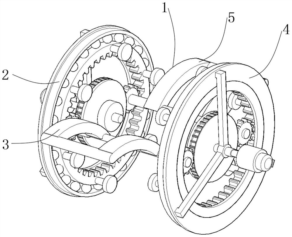
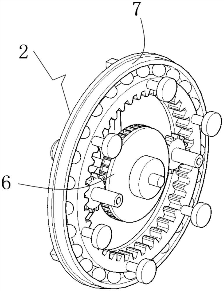
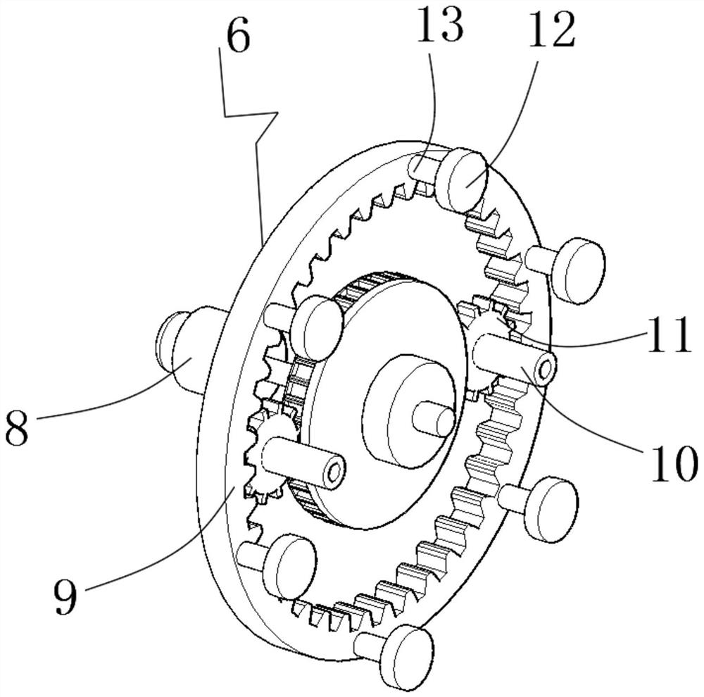
[0023] see Figure 1-6, the present invention provides a technical solution: a blocking mechanism for mechanical transmission, including a blocking mechanism main body 1, a first driving frame 2 is provided on the inner end side of the blocking mechanism main body 1, and one end of the first driving frame 2 is gear-engaged and connected There is a first blocking plate 3, the other end of the first driving frame 2 is gear-engaged with a second blocking plate 5,...


PUM


Abstract

The invention discloses a barrier mechanism for mechanical transmission. The barrier mechanism comprises a barrier mechanism main body, a first driving frame is arranged on one side of the inner end of the barrier mechanism main body, a first barrier plate is connected to one end of the first driving frame in a gear meshing mode, a second barrier plate is connected to the other end position of thefirst driving frame in a gear meshing mode, and a second driving frame is connected to the side end positions of the first barrier plate and the second barrier plate in a meshing mode; the inner endof the first driving frame comprises a driving frame and a stable frame, the driving frame is rotatably connected at the central position of the first driving frame, the stable frame is fixedly connected at the side end position of the driving frame, the driving frame comprises a power shaft frame, a driven gear plate, a sleeve frame, a connecting gear plate, a pushing shaft and a fixed frame, andthe power shaft frame is arranged at the central position of the driving frame. According to the barrier mechanism for mechanical transmission, the purpose of inner end barrier is achieved through the arrangement of the first driving frame and the second driving frame.

Description

technical field [0001] The invention relates to the technical field of mechanical equipment, in particular to a barrier mechanism for mechanical transmission. Background technique [0002] The barrier mechanism for mechanical transmission can be used for the purpose of barrier in mechanical transmission. Through the setting of the barrier mechanism for mechanical transmission, it can help to carry out intermittent feeding and meet the daily processing needs. At the same time, through regulation and control, the optimal connection between processes can be realized. , which helps to improve the efficiency of production. Through regulation, it can meet the loading and processing technology in the later stage, so that the mechanical objects can be arranged and combined according to batches, which is convenient for detection purposes. However, the barrier mechanism for mechanical transmission currently has the following problems, which are inconvenient. The phenomenon of stable r...

Claims


Application Information

Patent Timeline
Patent Type & Authority Applications(China)
IPC IPC(8): B65G47/88
CPCB65G47/88
Inventor 杨发陆
Owner 杨发陆
Why Eureka
Try Eureka