Light disk signal processing method and light disk device
A signal processing and signal technology, applied in the direction of recording signal processing, optical disc, optical recording/reproduction, etc., can solve the problems of high power consumption and high cost
- Summary
- Abstract
- Description
- Claims
- Application Information
AI Technical Summary
Problems solved by technology
Method used
Image

Examples
Embodiment 1
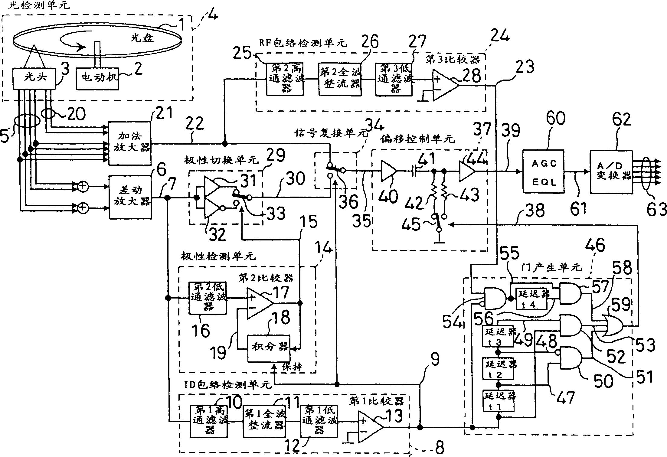
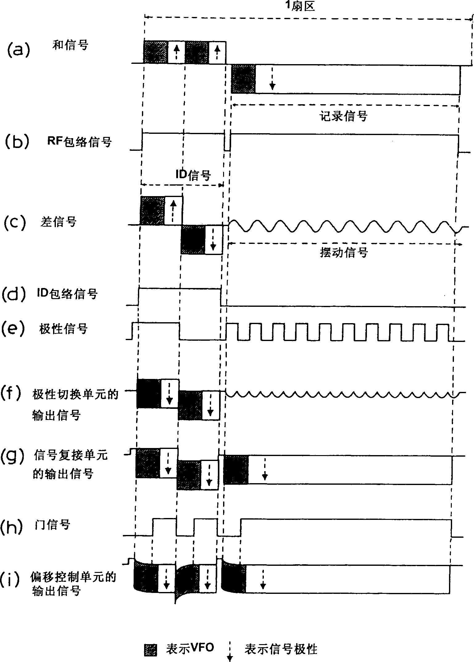
[0021] The optical disc device of Embodiment 1 of the present invention is shown in figure 1 , and its signal waveform is shown in image 3 .
[0022] figure 1 Among them, the light detection unit 4 is composed of an optical disc 1 , a motor 2 for rotating the optical disc 1 , and a detector (optical head) 3 for reading a signal from the optical disc 1 . Optical disc 1 is a rewritable optical disc with a land groove recording method with a phase change film. A pre-pit is engraved on the sector header, and an ID signal is arranged at the junction of the land and the groove. The latter have recorded signals as crystalline and amorphous marks. The optical head 3 irradiates the laser spot for focusing and tracking control on the flat land or groove of the optical disc 1, and the reflected light of the optical disc is received by a plurality of PIN diodes, converted into electrical signals and output. The differential amplifier 6 takes as its input the tracking signal 5 among t...
Embodiment 2
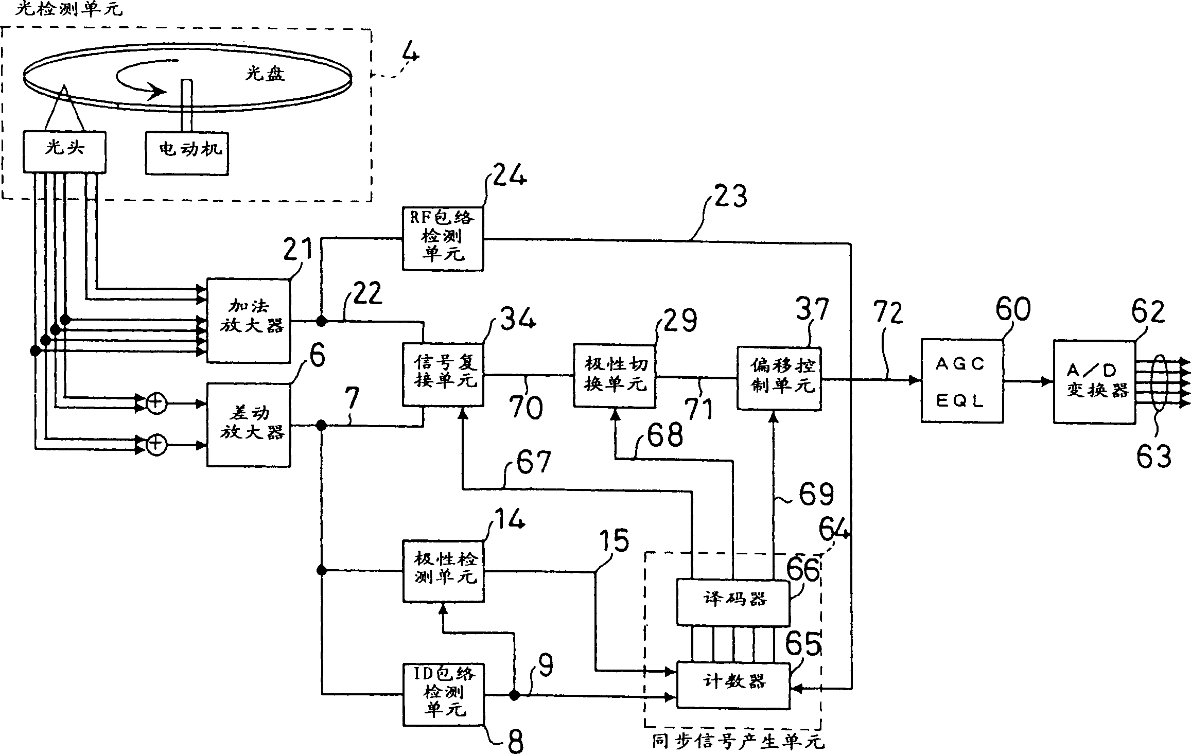
[0063] First, the optical disc device of the second embodiment in which the ID signal is selected from the difference signal will be described. The signal waveform diagram is shown in Figure 5 .
[0064] The description of the same configuration of the second embodiment as that of the first embodiment will be omitted, and only the differences between the two will be described. figure 2 in addition with figure 1 Frames with the same numbers have the same functions as those in Embodiment 1.
[0065] figure 2 Among them, the light detection unit 4 converts the signal recorded on the optical disc into a plurality of electrical signals for output. A difference signal 7 is generated by a differential amplifier 6 . Such as Figure 5 As shown in (c), the difference signal 7 is preceded by an ID signal and followed by a wobble signal of a single frequency. The ID signal is composed of two parts with different polarities, and the figure shows the situation opposite to that of E...
Embodiment 3
[0085] The optical disc device of Embodiment 3 of the present invention is shown in Figure 6 , and its signal waveform is shown in Figure 8 .
[0086] The description of the same parts of the third embodiment and the second embodiment is omitted, and only the different parts are described. Figure 6 in addition with figure 2 Blocks with the same numbers have the same functions as in Embodiment 2.
[0087] Figure 6 Among them, the light detection unit 4 converts the signal recorded on the optical disc into a plurality of electrical signals for output. Here, the detection method of the tracking signal 5 will be described.
[0088] Such as Figure 7 As shown, the optical head 3 uses a split detector 94 composed of detectors 3a to 3d arranged close to each other, and a receiving beam 95 is arranged at the junction thereof. The detection signals of the four detectors are output as t1-t4 signals.
[0089] Figure 6 Among them, the signal added by t1 and t4 is the tracki...
PUM
 Abstract
Description
Claims
Application Information