An automated cable laying device

A cable laying and transmission belt technology, which is applied in the direction of cable laying equipment, cable installation, ground cable installation, etc., can solve the problems of low efficiency of manual cable laying, and achieve the effect of flat ground, simple control circuit and faster speed

Active Publication Date: 2021-07-13
宁波谦屹节能科技有限公司
View PDF0 Cites 0 Cited by
  • Summary
  • Abstract
  • Description
  • Claims
  • Application Information

AI Technical Summary

Problems solved by technology

[0004] The purpose of the present invention is to solve the shortcomings of low efficiency of manual cable laying in the prior art, and propose an automatic cable laying device

Method used


Image

  • An automated cable laying device
  • An automated cable laying device
  • An automated cable laying device

Examples


Embodiment Construction

[0025] The following will clearly and completely describe the technical solutions in the embodiments of the present invention with reference to the accompanying drawings in the embodiments of the present invention. Obviously, the described embodiments are only some, not all, embodiments of the present invention.

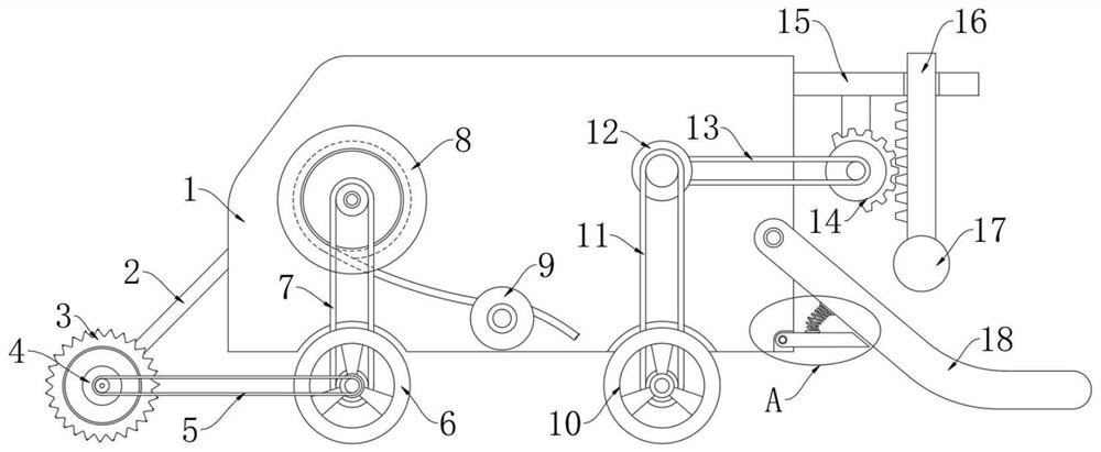
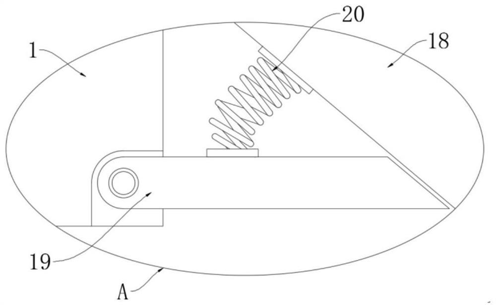
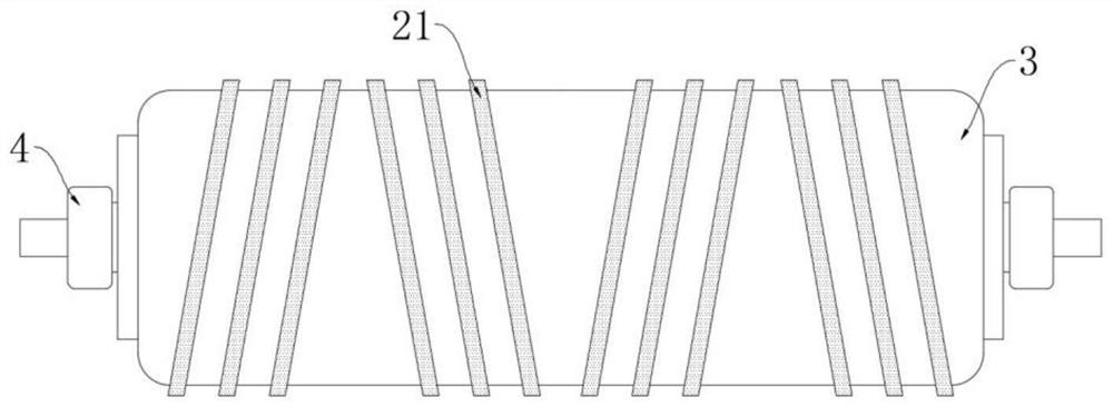
[0026] refer to Figure 1-4 , an automatic cable laying device, including a fuselage 1, a driving wheel 6 and a driven wheel 10, the front side of the fuselage 1 is rotatably connected with a crushing roller 3 through two obliquely arranged fixed rods 2, and the fixed rod 2 is close to the machine One end of the body 1 is fixedly connected with the fuselage 1 to serve as a crushing roller 3. The inner wall of the fuselage 1 is installed with a roll 8 through bearing rotation, and the cables to be laid are wound on the roll 8. A first transmission belt 5 is provided between the driving wheel 6 and the crushing roller 3, a second transmission belt 7 is provided between...


PUM


Abstract

The invention discloses an automatic cable laying device, which comprises a fuselage, a driving wheel and a driven wheel. The front side of the fuselage is rotatably connected with a crushing roller through two obliquely arranged fixed rods. The bearing is rotated and installed with a rolling roller, a first transmission belt is provided between the driving wheel and the crushing roller, a second transmission belt is provided between the driving wheel and the winding roller, and a flattening mechanism is provided on the rear side of the fuselage. A reversing device is provided between the flat covering mechanism and the driven wheel. The flat covering mechanism includes a flat pushing device and a striking device. The flat pushing device includes a flat covering plate hinged in the middle of the The baffle plate at the bottom of the body, the flat cladding plate includes an inclined end and a horizontal end. The invention only needs one power source to complete the processes of trench opening, cable laying, and ground levelling, which not only reduces the labor cost during construction, but also greatly speeds up the cable laying speed, thereby realizing automatic cable laying.

Description

technical field [0001] The invention relates to the technical field of cable laying, in particular to an automatic cable laying device. Background technique [0002] The laying of power cables is an important link in the construction of the national power grid. There are three main ways of laying power cables: pipeline, tunnel and direct burial. Among them, the laying of long-distance power cables is mostly direct burial to ensure signal of stability. [0003] Traditional direct-buried cable laying work is mostly done manually, and the general steps are as follows: use excavation equipment to dig a ditch; use multiple people to cooperate to lay the cable flat in the ditch; manually fill the earth back into the ditch; It can be seen from the above that the efficiency of manual laying is extremely low and takes a long time to compact the soft ground. Therefore, we propose an automatic cable laying device. Contents of the invention [0004] The object of the present inventi...

Claims


Application Information

Patent Timeline
Patent Type & Authority Patents(China)
IPC IPC(8): H02G1/06H02G9/00H02G9/02E02F5/02E02F5/10
CPCE02F5/02E02F5/10H02G1/06H02G9/00H02G9/02
Inventor 林峰
Owner 宁波谦屹节能科技有限公司
Why Eureka
Try Eureka