Combined U-shaped ring convenient to disassemble and assemble
A combined, U-shaped technology, applied in the direction of cable suspension devices, electrical components, etc., can solve the problems of complex installation process, inconvenient operators, simple structure, etc., and achieve a high degree of integration, convenient and fast installation and operation. simple effect
- Summary
- Abstract
- Description
- Claims
- Application Information
AI Technical Summary
Problems solved by technology
Method used
Image

Examples
Embodiment 1
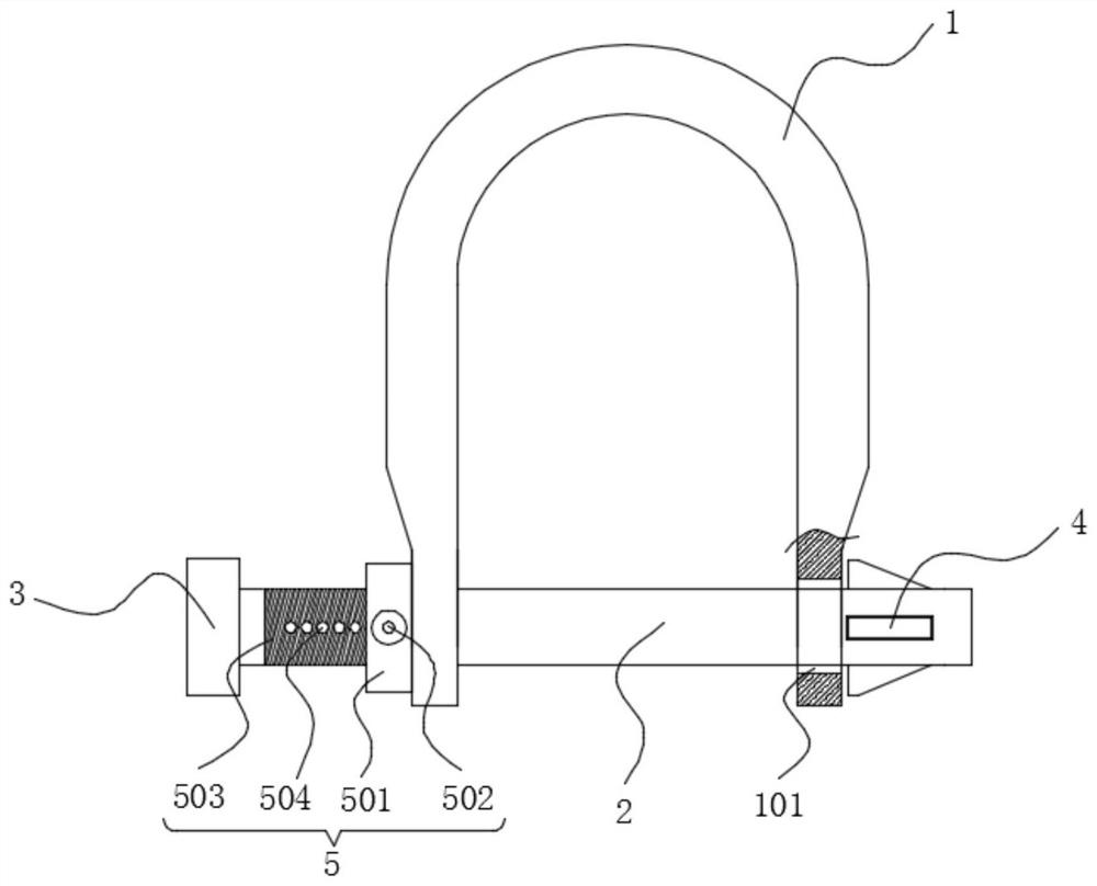
[0027] refer to figure 1 , 4 -6. A combined U-shaped ring that is easy to assemble and disassemble, including a U-shaped ring body 1 and a fastening rod 2. The U-shaped ring body 1 is an integrally formed casting structure, and both ends of the U-shaped ring body 1 are provided with limited positions. Hole 101, one end of the fastening rod 2 is fixedly provided with a limiting cap 3, the other end of the fastening rod 2 is provided with an elastic clamping mechanism 4, and the fastening rod 2 is connected to the U-shaped ring body 1 through two limiting holes 101 , the limit caps 3 at both ends of the fastening rod 2 and the elastic clamping mechanism 4 limit and fix it at both ends of the U-shaped ring body 1 .
[0028] The elastic clamping mechanism 4 includes a triangular clamping block 403, a telescopic slot 401 and a spring 402. At least one telescopic slot 401 is provided on the side wall of the fastening rod 2 away from the limit cap 3, and the bottom of the triangular...
Embodiment 2
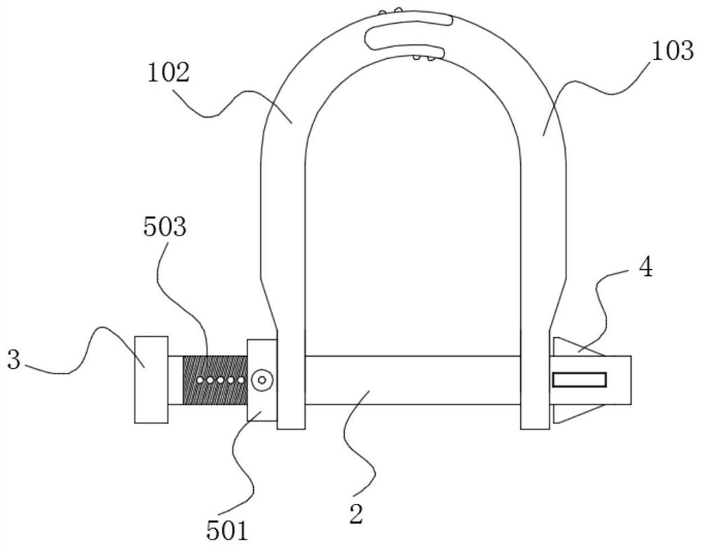
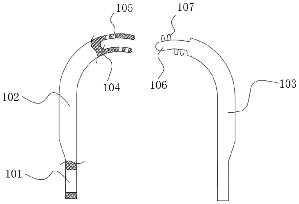
[0032] refer to figure 2 and 3 The difference between this embodiment and Embodiment 1 is that the structure of the U-shaped ring body 1 is different. The U-shaped ring body 1 includes a left ring body 102 and a right ring body 103, and the left ring body 102 and the right ring body 103 are assembled to form a U-shaped ring body. U-shaped ring structure, the two ends of the opening of the U-shaped ring structure are provided with limiting holes 101.
[0033] The end of the left ring body 102 away from the limit hole 101 is provided with an arc groove 104, and the staggered sides of the arc groove 104 are provided with fixing holes 105; the end of the right ring body 103 away from the limit hole 101 is provided with an arc groove 104 coincides with the arc-shaped plate 106, and the two sides of the arc-shaped plate 106 are alternately provided with elastic telescopic clamping blocks 107 matched with the fixing holes 105.
[0034] In this embodiment, when splicing the left ri...
Embodiment 3
[0036] refer to figure 1 , 3 and 4. The difference between this embodiment and Embodiment 1 or Embodiment 2 is that a locking assembly 5 is added. In this embodiment, the locking assembly 5 includes a limit nut 501 and a threaded section 503. A section of the solid rod 2 is close to the limit cap 3 , and the limit nut 501 is screwed and installed on the fastening rod 2 through the threaded section 503 .
[0037] The fastening rod 2 is located at the threaded section 503 and is provided with a plurality of positioning holes 504 along its length direction. The limiting nut 501 is provided with a positioning pin 502 penetrating through its side wall and inserted into the positioning holes 504 .
[0038] In this embodiment, after the fastening rod 2 is assembled with the U-shaped ring body 1, the stop nut 501 is rotated so that the stop nut 501 and the triangular block 403 are limited to the two ends of the U-shaped ring body 1. At this time, the positioning pin It is inserted i...
PUM
 Abstract
Description
Claims
Application Information
 - R&D
- Intellectual Property
- Life Sciences
- Materials
- Tech Scout
- Unparalleled Data Quality
- Higher Quality Content
- 60% Fewer Hallucinations
Browse by: Latest US Patents, China's latest patents, Technical Efficacy Thesaurus, Application Domain, Technology Topic, Popular Technical Reports.
© 2025 PatSnap. All rights reserved.Legal|Privacy policy|Modern Slavery Act Transparency Statement|Sitemap|About US| Contact US: help@patsnap.com