Deicing equipment for frozen pears
A frozen pear and equipment technology, applied in the field of deicing equipment, can solve the problems of reduced work efficiency, inconsistent force, easy soreness, etc., and achieve the effect of high work efficiency, consistent deicing effect, and consistent force
- Summary
- Abstract
- Description
- Claims
- Application Information
AI Technical Summary
Problems solved by technology
Method used
Image
Examples
Embodiment 1
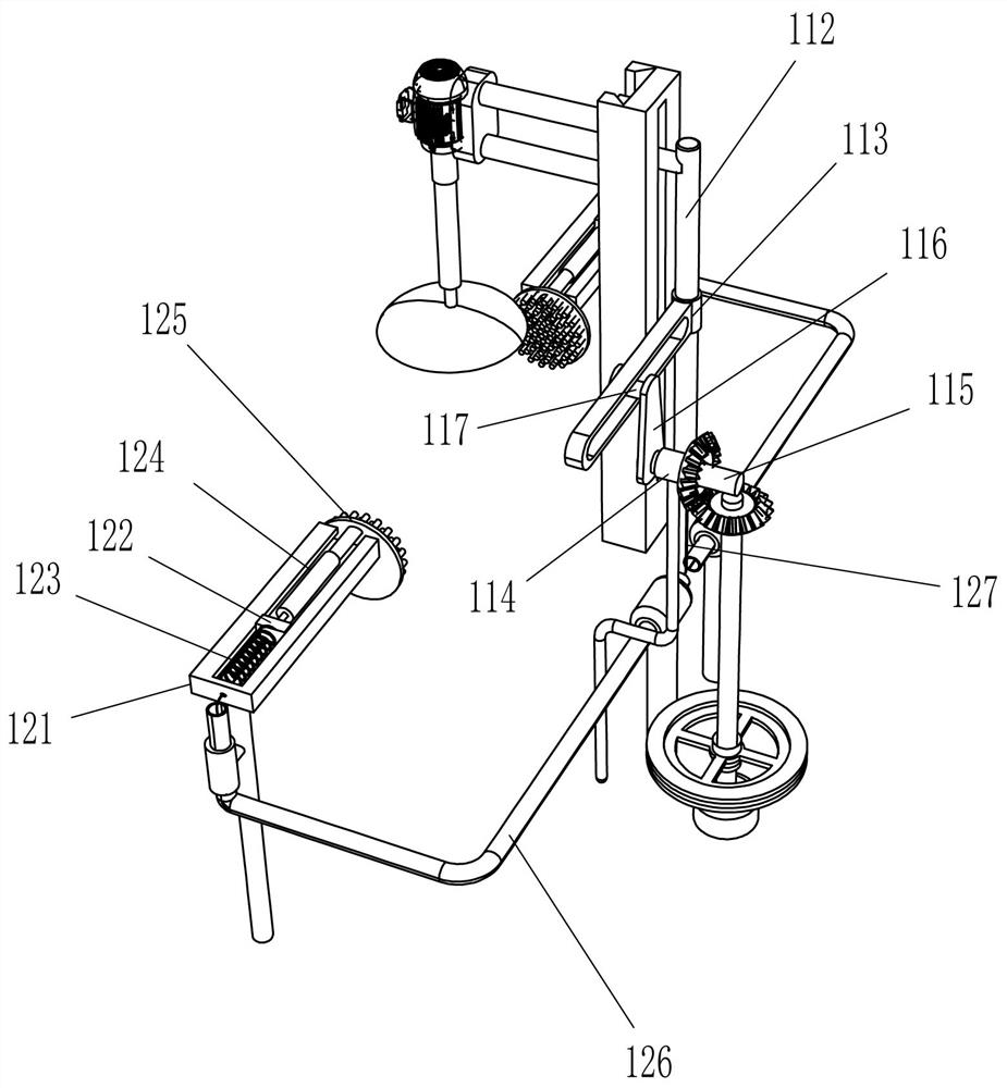
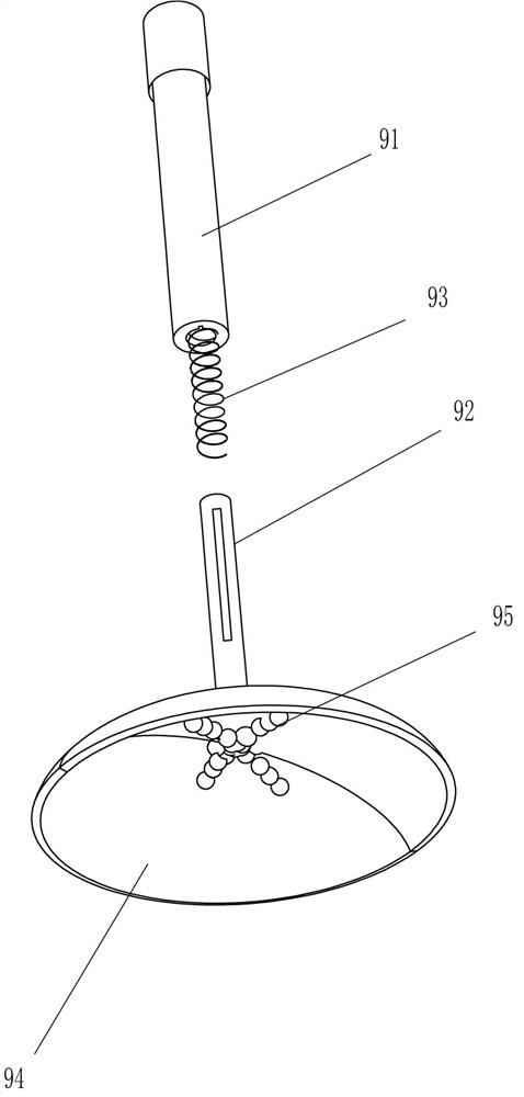
[0026] see Figure 1-Figure 4, a device for deicing frozen pears, including a base 1, a first rotating shaft 2, a mounting plate 3, a friction block 5, a first sliding rail 6, a first sliding block 7, a mounting frame 8, a first wiping mechanism 9, a servo The motor 10, the lifting mechanism 11 and the second wiping mechanism 12, the top of the base 1 is connected with the first rotating shaft 2 in a rotating manner, the upper part of the first rotating shaft 2 is fixedly connected with the mounting plate 3, and the top of the mounting plate 3 is evenly spaced with three recesses. Groove 4, the friction block 5 is fixedly connected in the groove 4, the first slide rail 6 is vertically installed in the middle of the left side of the top of the base 1, and the first slide rail 6 is provided with the first slide block 7 in a sliding type. Block 7 right side is fixedly connected with mounting frame 8, and mounting frame 8 right side is equipped with servomotor 10 by the mode of bo...
Embodiment 2
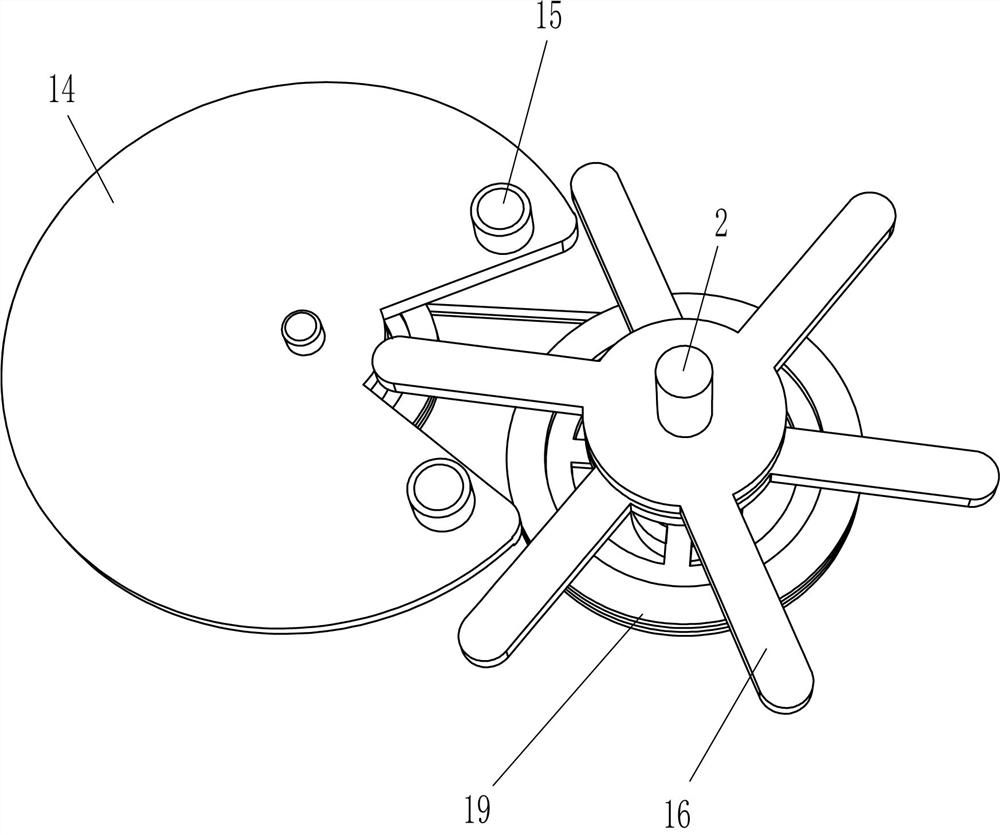
[0035] see figure 1 , Figure 5 with Image 6 Compared with Embodiment 1, the main difference of this embodiment is that this embodiment also includes a second rotating shaft 13, a fan-shaped plate 14, a top block 15, a triangular shifting plate 16, a third rotating shaft 17, and a first bevel gear 18. And the first belt transmission mechanism 19, the middle rotation type on the left side of the top of the base 1 is connected with a third rotating shaft 17, the third rotating shaft 17 is located between the mounting seat 118 and the bearing seat 114, the third rotating shaft 17 top and the rotating shaft 115 middle part are all The first bevel gear 18 is fixedly connected, and the first bevel gears 18 on the upper and lower sides are meshed. The middle of the left side of the top of the base 1 is connected with the second rotating shaft 13 in a rotating manner. The second rotating shaft 13 is located under the mounting plate 3. The second rotating shaft 13 A first belt trans...
Embodiment 3
[0038] see figure 1 with Figure 7 Compared with Embodiment 1 and Embodiment 2, the main difference of this embodiment is that this embodiment also includes a lower hopper 20, a fourth rotating shaft 21, a guide sleeve 211, a cylinder 22, a slideway 24, and a fifth rotating shaft 25. , the second bevel gear 26 and the second belt transmission mechanism 27, the lower hopper 20 is installed on the rear side of the top of the base 1, the lower part of the front side of the lower hopper 20 is fixedly connected with a slideway 24, the slideway 24 is inclined, and the slideway 24 and the concave The slot 4 cooperates, and the right side of the top in the lower hopper 20 is fixedly connected with a guide sleeve 211, and the inner rotation of the guide sleeve 211 is connected with a fourth rotating shaft 21, and the left part of the fourth rotating shaft 21 is fixedly connected with a cylindrical tube 22, and the cylindrical tube 22 and the lower The inner and lower parts of the hopp...
PUM
 Abstract
Description
Claims
Application Information
 - R&D
- Intellectual Property
- Life Sciences
- Materials
- Tech Scout
- Unparalleled Data Quality
- Higher Quality Content
- 60% Fewer Hallucinations
Browse by: Latest US Patents, China's latest patents, Technical Efficacy Thesaurus, Application Domain, Technology Topic, Popular Technical Reports.
© 2025 PatSnap. All rights reserved.Legal|Privacy policy|Modern Slavery Act Transparency Statement|Sitemap|About US| Contact US: help@patsnap.com


