
Bridge plate pier connecting structure of prefabricated bridge

A technology for connecting structures and prefabricated bridges, applied in bridges, bridge parts, bridge construction, etc., can solve problems such as poor vibration isolation effect, and achieve the effect of good lateral movement resistance and not easy to be corroded and damaged

Active Publication Date: 2020-09-18
JIANGSU SUJIAN ROAD & BRIDGE MASCH CO LTD
View PDF19 Cites 0 Cited by
  • Summary
  • Abstract
  • Description
  • Claims
  • Application Information

AI Technical Summary

Problems solved by technology

[0004] The invention provides a prefabricated bridge slab and pier connection structure with good anti-lateral displacement and vibration isolation effect, which solves the problem of poor vibration isolation effect between the existing prefabricated assembled bridge slab and bridge pier

Method used


Image

  • Bridge plate pier connecting structure of prefabricated bridge
  • Bridge plate pier connecting structure of prefabricated bridge
  • Bridge plate pier connecting structure of prefabricated bridge

Examples


Embodiment 1

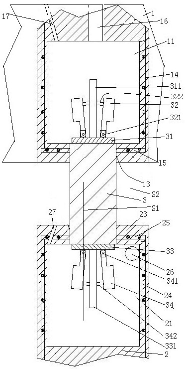
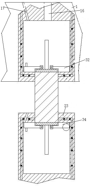
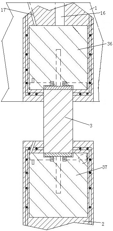
[0023] Embodiment one, see figure 1 , figure 2 and image 3 , a bridge deck pier connection structure of a prefabricated bridge, comprising a bridge deck 1, bridge piers 2 and rubber support rods 3.

[0024] An upper assembly hole 11 is provided on the lower end surface of the bridge plate 1 . The opening of the upper assembly hole is integrally formed with an upper assembly hole annular cover 13 . The hole wall of the upper assembly hole is provided with a reinforcement frame 14 on the side wall of the upper assembly hole. The upper hole cover part reinforcement frame 15 is provided in the upper assembly hole annular cover. The upper assembly hole is provided with a pouring hole 16 for the bridge part and an exhaust hole 17 for the bridge part. Both the pouring holes of the bridge plate and the exhaust holes of the bridge plate pass through the upper surface of the bridge plate.

[0025] The lower end surface of the pier 2 is provided with a lower assembly hole 21 . T...

Embodiment 2

[0029] Embodiment two, the difference with embodiment one is:

[0030] see Figure 4 , the lower assembly hole annular cover is provided with permanent magnet 35. After the rubber support rod stretches in, under the effect of the permanent magnet 35, the lower hook connecting rod is turned over and overlapped on the lower assembly hole annular cover. There is no need for artificial magnets to attract and turn over, which improves the convenience of construction.


PUM


Abstract

The invention relates to a bridge plate pier connecting structure of a prefabricated bridge. The bridge comprises a bridge deck, bridge piers and rubber support rods, the lower end face of the bridgedeck is provided with an upper assembling hole and a lower assembling hole. An upper assembly hole annular cover is arranged on the opening of the upper assembly hole to form the upper assembly hole annular cover; a lower assembly hole annular cover is arranged on the opening of the assembly hole to form the lower assembly hole annular cover; a plurality of upper hooking rods are hinged to the upper ends of the rubber supporting rods, and a plurality of lower hooking rods are hinged to the lower ends; the upper end of the rubber supporting rod is arranged in the upper assembling hole annular cover in a penetrating mode, and the upper hooking rod is hooked to the upper assembling hole annular cover; concrete is poured into the upper assembling holes, the lower ends of the rubber supportingrods are arranged in the lower assembling hole annular covers in a penetrating mode, the lower hooking rods are hooked to the lower assembling hole annular covers, concrete is poured into the lower assembling holes, and gaps are formed between the bridge deck and the bridge piers. The connecting structure has the advantages of extrusion lateral displacement resistance and vibration resistance, sothat the problem that the vibration isolation effect between layers of an existing assembled concrete structure is poor is solved.

Description

[0001] This application is a divisional application of the application date of December 11, 2018, application number 2018115138934, and the name "bridge slab and pier connection structure of a prefabricated bridge". technical field [0002] The invention relates to bridges, in particular to a bridge plate and pier connection structure of a prefabricated bridge. Background technique [0003] Bridge construction is important in the construction of highways, high-speed railways and urban viaducts. In bridge construction, there are only two ways to construct bridge slabs: one is prefabricated installation construction, and the other is on-site pouring construction. Prefabricated installation construction is to decompose the bridge slab into units and make them in factories or prefabrication yards, and then transport the units that make up the bridge slab to the location of the bridge and install them on the piers. The advantages of this bridge construction method are: the bridge...

Claims


Application Information

Patent Timeline
Patent Type & Authority Applications(China)
IPC IPC(8): E01D19/00E01D19/04
CPCE01D19/00E01D19/04
Inventor 不公告发明人
Owner JIANGSU SUJIAN ROAD & BRIDGE MASCH CO LTD
Learn More