Hydrostatic bearing

A hydrostatic bearing and pressure sensor technology, applied in the direction of bearings, shafts and bearings, mechanical equipment, etc., can solve the problems of increasing radial offset, affecting the accuracy of the spindle, reducing the thickness of the oil film, etc. The effect of improving the rigidity of the oil film and improving the rotation accuracy

Inactive Publication Date: 2020-09-18
杭州中奥工业设计有限公司
View PDF12 Cites 2 Cited by
  • Summary
  • Abstract
  • Description
  • Claims
  • Application Information

AI Technical Summary

Problems solved by technology

When the load becomes larger, the radial offset of the spindle will increase, and when the precision requirement is high, it will affect the precision of the spi

Method used


Image

  • Hydrostatic bearing
  • Hydrostatic bearing
  • Hydrostatic bearing

Examples


Embodiment Construction

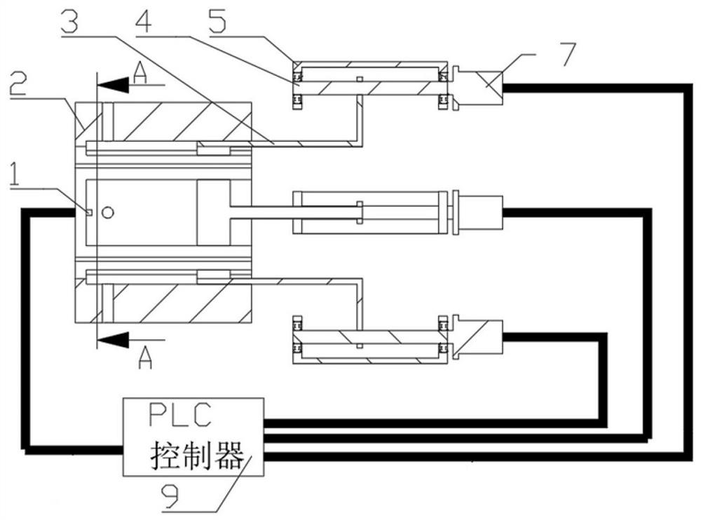
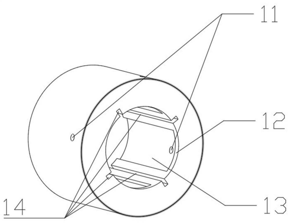
[0019] refer to Figure 1-3 , a hydrostatic bearing 2, comprising several oil chambers, the several oil chambers are uniformly arranged on the inner wall surface of the hydrostatic bearing, each of the several oil chambers includes an oil chamber adjustment mechanism, Each of the oil chamber regulating mechanisms works independently, and the oil chamber regulating mechanism dynamically adjusts the volume of the oil chamber according to the pressure of the oil chamber.

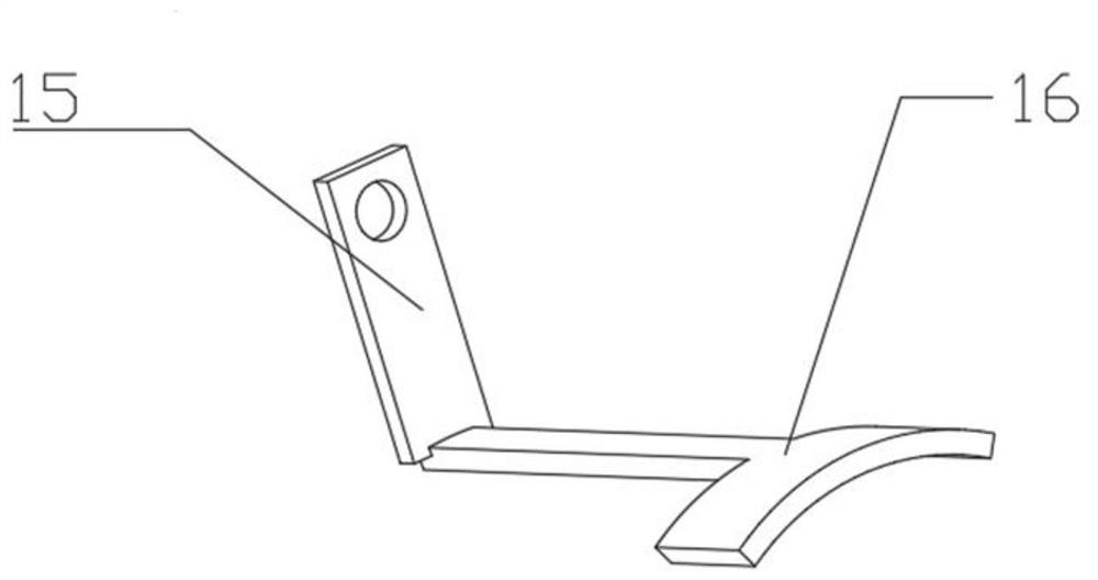
[0020] The oil chamber adjustment mechanism includes an adjustment plate 16, a connecting rod 15, a screw nut mechanism and a motor 7. The adjustment plate 16 is located inside the oil chamber, and the outer contour of the adjustment plate 16 matches the inner contour of the oil chamber. The adjustment plate 16 One end outside the oil chamber is fixedly connected with a connecting rod 15, the connecting rod 15 is connected with the nut in the screw nut mechanism, the leading screw is fixed by the leading screw ...


PUM


Abstract

The invention discloses a hydrostatic bearing. The hydrostatic bearing comprises several oil cavities, wherein the oil cavities are uniformly formed in the inner wall face of the hydrostatic bearing,each oil cavity comprises an oil cavity adjusting mechanism (3) which works independently, and the oil cavity adjusting mechanisms dynamically adjust the size of the corresponding oil cavities according to the pressure of the oil cavities. According to the hydrostatic bearing, when the loads of a main shaft change, resultant force opposite to the change direction of the loads can be actively produced to reduce the offset generated by the main shaft, and the position accuracy of the main shaft is guaranteed accordingly.

Description

technical field [0001] The invention belongs to the technical field of static pressure bearings, and in particular relates to a static pressure bearing which can automatically adjust the size of an oil chamber according to the size of the load. Background technique [0002] Hydrostatic bearing is a kind of sliding bearing with high precision and large load, which is widely used in machinery industry. Traditional hydrostatic bearings rely on externally supplied pressure oil to form an oil film between the spindle and the bearing, and use the oil film to bear the load. There are 4 or 6 oil chambers evenly opened on the inner wall of the hydrostatic bearing, and each oil chamber maintains a certain pressure, so that a certain thickness of oil film is maintained between the main shaft and the bearing to ensure that the bearing is in normal working conditions. When the main shaft is subjected to external force, the main shaft will deviate, and the pressure of each oil chamber wi...

Claims


Application Information

Patent Timeline
IPC IPC(8): F16C32/06
CPCF16C32/0648
Inventor 平巧丽
Owner 杭州中奥工业设计有限公司
Why Eureka
Try Eureka