
Water level monitoring device for water conservancy project

A water level monitoring device and water conservancy engineering technology, which is applied in the direction of buoy liquid level indicators, etc., can solve the problems of increasing the workload of staff, issuing warnings and reminding staff, and failing to meet the needs of water level monitoring, so as to improve the performance and scope of application Effect

Pending Publication Date: 2020-09-18
李杨
View PDF0 Cites 1 Cited by
  • Summary
  • Abstract
  • Description
  • Claims
  • Application Information

AI Technical Summary

Problems solved by technology

Water level monitoring is mainly to monitor the water depth of water bodies in dams, canals, rivers, etc. At present, water level monitoring mostly adopts methods such as setting up benchmarks or marking water level warning lines on the inclined wall of the dam body to warn the current water level. The structures of the devices used are relatively simple, but at the same time there is a problem that, during the monitoring process, when the water level of the water body reaches the warning water level, neither of these two methods can automatically (or actively) send a warning to the staff Therefore, the staff must frequently check the water level of the water body at regular intervals, which not only greatly increases the workload of the staff, but also cannot find the location exceeding the warning water level quickly enough and in time for follow-up treatment, so that it cannot Meet better meet current water level monitoring needs

Method used


Image

  • Water level monitoring device for water conservancy project
  • Water level monitoring device for water conservancy project
  • Water level monitoring device for water conservancy project

Examples


Embodiment Construction

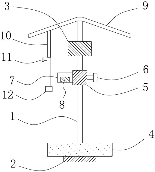
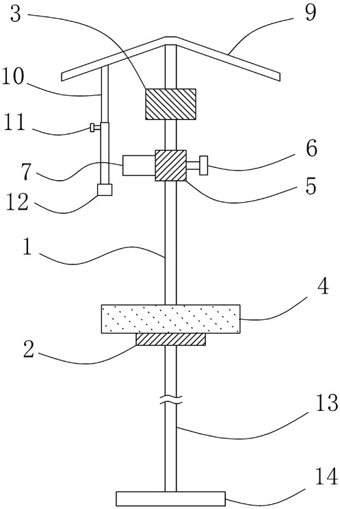
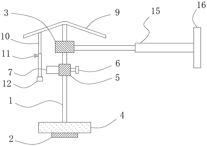
[0027] Such as figure 1 Shown is a schematic structural diagram of a water level monitoring device for a water conservancy project. The device includes a vertically arranged slide bar 1, a circular stopper chassis 2 is threaded at the bottom end of the slide bar 1, and a bottom inner threaded hole (not shown in the figure) is opened at the bottom center of the stopper chassis 2 ), the top limit block 3 is fixed on the top of the slide bar 1, and the floating block 4 and the installation block 5 are respectively slidably sleeved on the slide bar 1. The installation block 5 is located above the floating block 4, and The mounting block 5 is also provided with a first fastening knob 6;

[0028] A monitoring box 7 with a bottom opening is also installed on the mounting block 5, and a storage battery for power supply and a monitoring module 8 for monitoring the distance between the monitoring box 7 and the floating block 4 are respectively provided inside the monitoring box 7, Suc...


PUM


Abstract

The invention relates to a water level monitoring device for a water conservancy project. The monitoring device comprises a slide bar, the bottom end of the sliding rod is in threaded fit with a limiting chassis; a top limiting block is fixedly arranged at the top end of the sliding rod; a floating block and a mounting block sleeve the sliding rod in a sliding manner; a monitoring box with an opening in the bottom end is mounted on the mounting block; a storage battery and a monitoring module are arranged in the monitoring box; the monitoring module comprises a distance sensing unit, a processing unit connected with the distance sensing unit and an alarm unit connected with the processing unit. A rainproof cover body is further arranged at the top end of the top limiting block, at least one vertically-arranged vertical telescopic rod is connected to the bottom end of the rainproof cover body, a second fastening rotary knob is arranged on the vertical telescopic rod, and meanwhile a check block is further fixedly arranged at the bottom end of the vertical telescopic rod. By adoption of the structure, the water level of a water body can be effectively monitored, a warning prompt is sent out actively, and therefore the use performance and the application range of the device are greatly improved.

Description

technical field [0001] The invention relates to a water level monitoring device for water conservancy projects. Background technique [0002] In the monitoring process of water conservancy projects, water level monitoring is an indispensable and important link. Water level monitoring is mainly to monitor the water depth of water bodies in dams, canals, rivers, etc. At present, water level monitoring mostly adopts methods such as setting up benchmarks or marking water level warning lines on the inclined wall of the dam body to warn the current water level. The structures of the devices used are relatively simple, but at the same time there is a problem that, during the monitoring process, when the water level of the water body reaches the warning water level, neither of these two methods can automatically (or actively) send a warning to the staff Therefore, the staff must frequently check the water level of the water body at regular intervals, which not only greatly increase...

Claims


Application Information

Patent Timeline
IPC IPC(8): G01F23/30
CPCG01F23/30
Inventor 李杨王佳李敏张艳吕绪明
Owner 李杨
Learn More