On-board fuel inerting system

a fuel inerting system and fuel technology, applied in the direction of machines/engines, transportation and packaging, liquid transfer devices, etc., can solve the problems of ozone depletion, 550 deaths, and inability to use halogen-based gases in commercial aircraft and general aviation

Inactive Publication Date: 2003-10-21
SUSKO KENNETH
View PDF12 Cites 91 Cited by
  • Summary
  • Abstract
  • Description
  • Claims
  • Application Information

AI Technical Summary

Benefits of technology

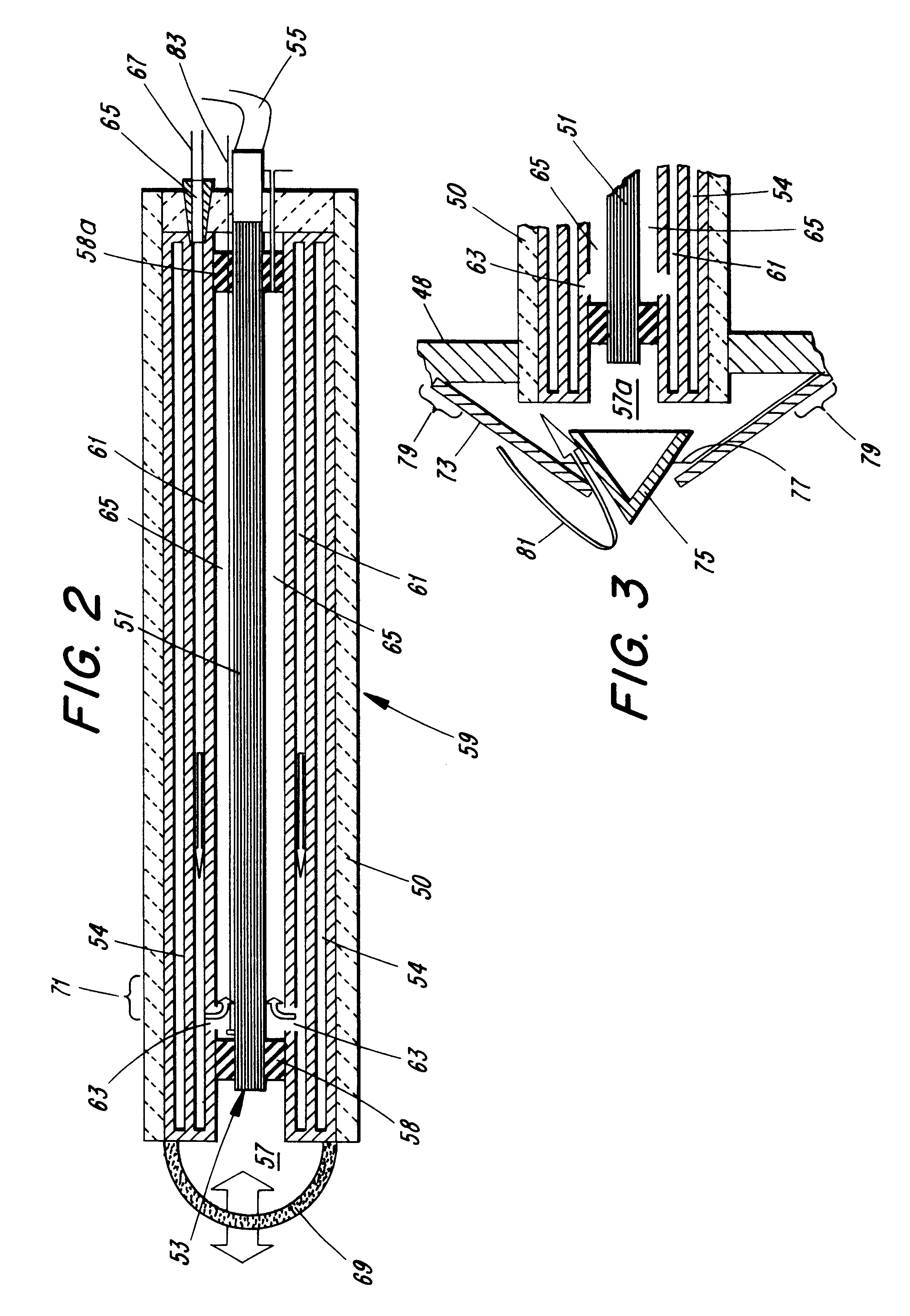
In particular, the instant invention provides a system that provides an inert blanket of a nitrogen rich gas atmosphere to a fuel tank or other environment so as to inert that environment from the prospect of explosion. In a further aspect of this invention there is provided a system with safe and effective monitoring of the oxygen concentration (preferably measured as oxygen partial pressure) in the atmosphere in a tank or other area to be inerted such that nitrogen can be metered efficiently from a liquid nitrogen source to maintain the atmosphere at a desirably low oxygen concentration so that the potential of explosion is minimized or eliminated. Temperature of the tank can also be monitored further to assess the potentially explosive character of the tank contents. There is further provided an effective probe which can effectively monitor the oxygen content of the atmosphere within a fuel tank, and which can accomplish that monitoring function accurately without introducing a danger that the probe itself can be a source of sparking that could initiate an explosion. In a special embodiment, the probe is a passive fiber optic probe that can be extended into the fuel tank or other environment to monitor oxygen content and provide a basis for controlling oxygen concentration. Because, in the particular embodiment of this invention, the output of the fiber optic probe indicative of oxygen concentration is temperature dependent, there is also provided herein a shroud or device to maintain the probe at a known uniform temperature in order to assure an accurate oxygen measurement can be obtained.
The system of the instant invention utilizes an on-board liquid nitrogen supply in the form of a dewar or similar liquid nitrogen-holding container which is suitably insulated to maintain the liquid nitrogen at reduced temperature for a long period. The container desirably is sized to provide a sufficient supply of nitrogen to blanket the fuel tank, for example the center wing tank or multiple fuel tanks of an aircraft, preferably several times over as will be explained below. The on board nitrogen supply is in valved fluid communication with the fuel tank or tanks or other environments to be inerted, most typically the aircraft's center wing tank. A passive fiber optic probe that extends into the tank monitors the oxygen partial pressure within the tank. The output from the probe can be fed to a spectrometer or similar instrument that is adapted to translate the analog output of the probe to a digital signal which can be fed to a suitable controller, such as a microprocessor-based controller. The microprocessor can then control valves through which nitrogen flows from the onboard nitrogen source to feed nitrogen to the tank as needed to maintain the over fuel atmosphere in an inerted condition. The apparatus can control that flow and maintain an inert condition by monitoring a signal from the probe and using software adaptations that will be understood by those skilled in the art to enable the microprocessor to control the nitrogen content in the ullage of the tanks.
The accurate probes contemplated by this invention provide an output signaling oxygen partial pressure that is temperature dependent, and hence the invention also provides a receptacle or shroud to provide a stable temperature environment which can be used in the case of a system which is subject to the widely varying temperatures the will be encountered by a commercial aircraft. That is, the invention provides a heated receptacle or well to encase the probe extending into the fuel tank to maintain the probe at a sufficiently constant temperature to assure accurate oxygen readings by the probe. The fuel tank is supplied with a suitable relief valve that will expel the over-fuel gas-vapor mixture as nitrogen is metered from the on board supply to the tank. The overall system, however can be operated at relatively low peak pressures of 20 psi over ambient or less. The system of this invention accordingly overcomes the disadvantages of some suggested systems that require compressors on board to effect nitrogen separation from air.
Accordingly, in summary, the instant invention provides an on-board fuel inerting system for a vehicle subject to electrical sparking or other intrusion of potentially explosive occurrences within a fuel tank of the vehicle which comprises: (a) an oxygen partial pressure detector maintained in contact with the vapors in the ullage of the fuel tank; (b) a source of inert gas maintained on-board the vehicle in valved communication with the ullage volume of the fuel tank; and (c) a controller responsive to the detection of a partial pressure of oxygen within said ullage volume that is higher than some predetermined level to cause inert gas to flow into the ullage volume from said source to establish the oxygen partial pressure below said predetermined level. In the preferred embodiments, the system is adapted to an aircraft using nitrogen gas as the inerting agent and using a fiberoptic oxygen-detecting probe which makes it possible to detect oxygen partial pressure within the tank without exposing the ullage volume to electricity and an additional source of sparking.

Problems solved by technology

Since 1959, there have been a number of explosions of the center wing tank on military and commercial aircraft reportedly resulting in deaths of as many as 550 persons.
But the use of halogen-based gases is not viable in commercial aircraft and in general aviation because of their effects resulting in ozone depletion.
The discussion in that article pointed out that, in particular, the center wing tank of commercial aircraft can reach high temperatures when the aircraft required to queue up on the hot tarmac of an airport at summer temperatures, and that such conditions have been linked to some explosions.

Method used


Image

  • On-board fuel inerting system
  • On-board fuel inerting system
  • On-board fuel inerting system

Examples


Embodiment Construction

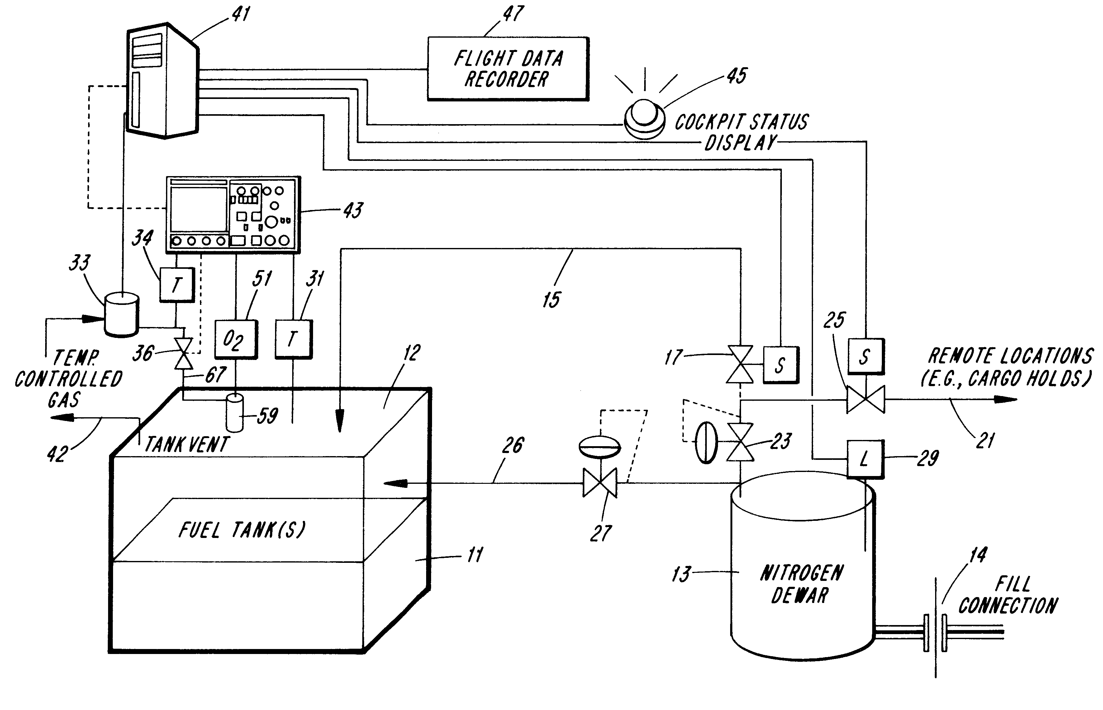
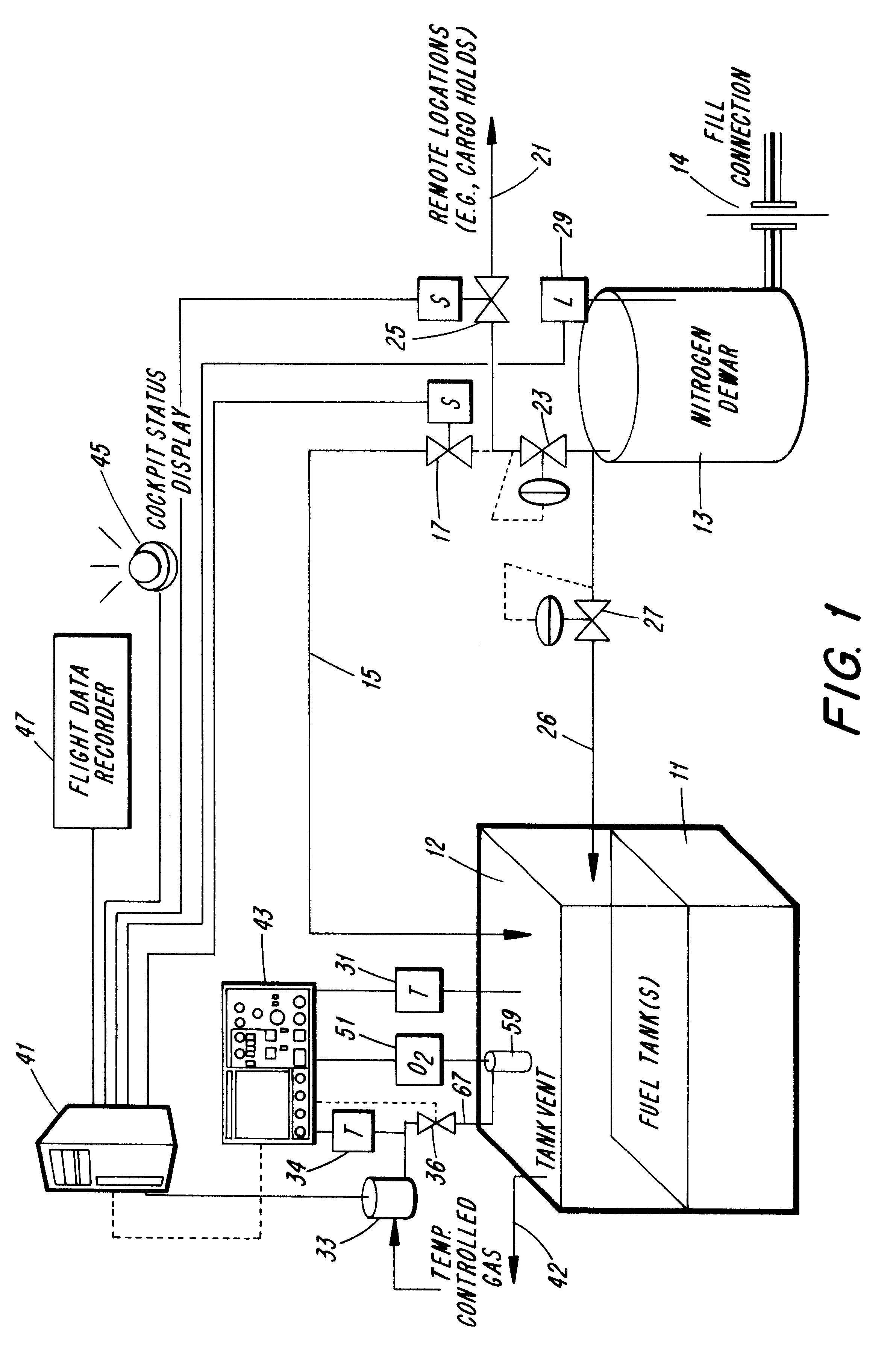
Referring to FIG. 1 there is shown schematically a fuel tank 11 having fuel in the lower portion thereof. The overfuel or ullage volume of the tank 12, also known as ullage, would accordingly be typically filled with an air-fuel vapor mixture which would very likely combustible and explosive if the fuel vapors were combined with ambient air. Nitrogen gas line 15 is capable of conducting nitrogen to the upper most portion of the tank, and is in valved communication with a nitrogen dewar 13. Any suitable insulated container may be used, however, a dewar container of the type typically used to store liquefied gases is preferred. Such container may have, for example, a double wall with evacuated space between the walls and reflective or silvered surfaces. Although any suitable insulative type container for storing liquefied gas may be used, the nitrogen container shall be referred to as a dewar herein.

In accordance with a particular aspect of the invention the supercooled liquid nitroge...


PUM


Abstract

An inerting system is disclosed that is adaptable to inert the fuel tank of a vehicle, most typically an aircraft, that includes an oxygen detector to monitor the oxygen partial pressure of the vapors in the ullage (i.e., the overfuel) volume of the tank, a source of an inert gas (e.g., nitrogen) in valved communication with the ullage of the tank, and a detector for sensing the oxygen content in the ullage of the tank and controlling the flow of inert gas to the tillage to maintain that volume with a proportion oxygen that will not support combustion in the event of an ignition source or intrusion of another potentially explosive occurrence within said tank. A specific fiberoptic probe which enables monitoring oxygen content within the tank without introducing a source of electrical current within the tank is also disclosed.

Description

This invention relates to a novel system for inerting combustible and potentially explosive fuel supplies in vehicles such as aircraft. More particularly, this invention provides a novel nitrogen fuel inerting system that will fill the ullage (i.e., the vaporous volume within a fuel tank above the liquid fuel) of an aircraft fuel tank or other fuel tank with an inert gas that will not support combustion. The invention concomitantly provides a capability of actively monitoring the oxygen content of vapor and gas in the ullage of a fuel tank to maintain the inert status of the over-fuel vapors and enable efficient dispensing of the inert gas.BACKGROUND AND PRIOR ARTSince 1959, there have been a number of explosions of the center wing tank on military and commercial aircraft reportedly resulting in deaths of as many as 550 persons. Those infrequent but continuing occurrences involving fuel tank explosions are believed to have possibly been caused by unknown sources of ignition, possibl...

Claims


Application Information

Patent Timeline
Patent Type & Authority Patents(United States)
IPC IPC(8): B64D37/32B64D37/00B60K15/00
CPCB64D37/32B60K15/00B60K2015/03381Y10T137/3127
Inventor SUSKO, KENNETH
Owner SUSKO KENNETH
Why Eureka
Try Eureka