Photoelectric combination cable mounting rack

A technology of cable installation and photoelectric combination, which is applied in the field of cables, can solve the problems of inconvenient adjustment of the position of the support frame, easily damaged skin, and classified collection, etc., to achieve the effect of increasing practicability, ensuring internal cleanliness, and increasing storage quantity

Pending Publication Date: 2020-09-18
崔亮
View PDF14 Cites 3 Cited by
  • Summary
  • Abstract
  • Description
  • Claims
  • Application Information

AI Technical Summary

Problems solved by technology

[0004] The purpose of the present invention is to provide a photoelectric composite cable mounting frame to solve the problem that the existing photoelectric composite cable installation only plays a supporting role in the above background technology, and it is not convenient to adjust the position of the support frame, and the cable is not integrated. Sorted collection, when installing and pulling the cable, it is easy to damage the skin, and the cable will fail in the later stage, and the cable tie needs to be processed before pulling

Method used


Image

  • Photoelectric combination cable mounting rack
  • Photoelectric combination cable mounting rack
  • Photoelectric combination cable mounting rack

Examples


Embodiment Construction

[0027] The following will clearly and completely describe the technical solutions in the embodiments of the present invention with reference to the accompanying drawings in the embodiments of the present invention. Obviously, the described embodiments are only some, not all, embodiments of the present invention. Based on the embodiments of the present invention, all other embodiments obtained by persons of ordinary skill in the art without making creative efforts belong to the protection scope of the present invention.

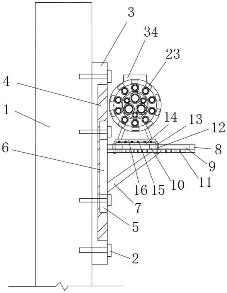
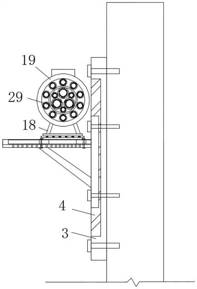
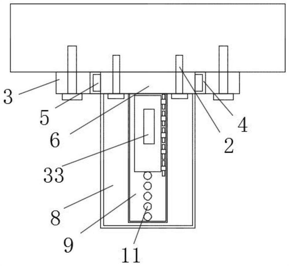
[0028] see Figure 1-8 , the present invention provides a technical solution: a photoelectric composite cable mounting frame, including a first fixing plate 3, such as figure 1 , image 3 and Figure 5 As shown, the first fixing plate 3 is threadedly fixed on the fixed wall surface 1 through the bolt 2, and the first fixing plate 3 is provided with a first slideway 4, and the first slideway 4 is slidably connected with a first slider 5. The first slideway 4...


PUM


Abstract

The invention discloses a photoelectric combination cable mounting rack. The mounting rack comprises a fixed wall surface and a control box, the fixed wall surface is in threaded connection with a first fixed plate through a bolt; a first slideway is formed in the first fixed plate; meanwhile, the first slideway is slidably connected with first sliding blocks; a second fixed plate is fixed betweenthe first sliding blocks; a supporting frame and a supporting rod are fixed to the right side of the second fixed plate. A second slideway is formed in the first supporting plate, a first spring shaft is fixed to the upper side of a third fixed plate, a second supporting plate is fixed to the upper side of the first spring shaft, threaded holes are formed in the second sliding block and the firstsupporting plate, and a cable mounting frame assembly is fixed to the upper side of the second supporting plate in a threaded mode. According to the photoelectric combination cable mounting rack, a sliding limiting assembly is arranged, an arc-shaped plate in the sliding limiting assembly can be adjusted under the effect of a second spring shaft, and balls are arranged on the arc-shaped plate sothat a cable can conveniently and rapidly penetrate through the space defined by the arc-shaped plate.

Description

technical field [0001] The invention relates to the technical field of cables, in particular to a photoelectric composite cable installation frame. Background technique [0002] A cable is an electrical energy or signal transmission device, usually a rope-like cable twisted by several or groups of wires (at least two in each group), each group of wires is insulated from each other, and often surrounds a Twisted in the center, the entire exterior is covered with a highly insulating cover. The cable has the characteristics of internal electrification and external insulation. [0003] The existing photoelectric combination cable installation frame is relatively common, and it only supports the cables, and it is not convenient to adjust the position of the support frame. Moreover, there are many cables in the underground duct bag, and the cables are not classified and collected as a whole. When the cable is installed and pulled, the cable directly rubs against the installation...

Claims


Application Information

Patent Timeline
Patent Type & Authority Applications(China)
IPC IPC(8): H02G3/30H02G9/06F16F15/067
CPCF16F15/067H02G3/30H02G9/06
Inventor 崔亮
Owner 崔亮
Why Eureka
Try Eureka