Mechanical stretching unit and mechanical stretching device

A technology for machinery and mounting plates, applied in the field of mechanical stretching units and mechanical stretching devices, can solve the problems of the chute and the component moving track is not smooth enough, the movement track cannot be smooth, and the user experience is reduced, so as to facilitate subsequent assembly and movement. Smooth, consistent stretch effect

Pending Publication Date: 2020-09-22
UE FURNITURE CO LTD
View PDF1 Cites 5 Cited by
  • Summary
  • Abstract
  • Description
  • Claims
  • Application Information

AI Technical Summary

Problems solved by technology

[0005] The above-mentioned seat unit can only be stretched, lifted and closed forcibly by the sliding long slot; thus, the stretching device cannot make the movement track of the product smooth because of the space gap of the slide slot. When leaning against the backrest, there will be a state of jumping or displacement, which greatly reduces the user's sense of experience
[0006] And in the process of folding or stretching the backrest, the plate where the chute is located relatively moves up or down to drive the parts used for cushion support to rotate. Since the cooperative movement track between the chute and the components is not smooth enough, the parts used for cushion support rotate. , there will also be jumping or displacement problems

Method used


Image

  • Mechanical stretching unit and mechanical stretching device
  • Mechanical stretching unit and mechanical stretching device
  • Mechanical stretching unit and mechanical stretching device

Examples


Embodiment Construction

[0046] In order to further understand the content of the present invention, the present invention will be described in detail in conjunction with the accompanying drawings and specific embodiments.

[0047] In describing the present invention, it is to be understood that the terms "center", "upper", "lower", "front", "rear", "left", "right", "vertical", "horizontal", The orientations or positional relationships indicated by "top", "bottom", "inner", "outer", etc. are based on the orientations or positional relationships shown in the drawings, and are only for the convenience of describing the present invention and simplifying the description, rather than indicating or implying the It should not be construed as limiting the invention that a device or element must have a particular orientation, be constructed, and operate in a particular orientation.

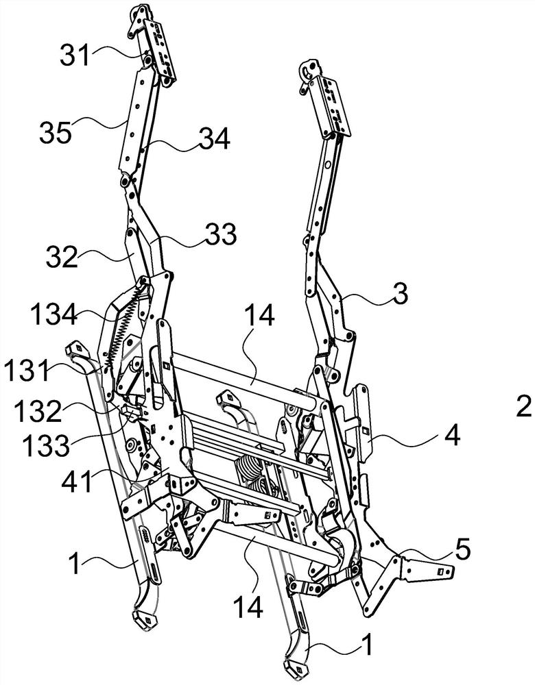
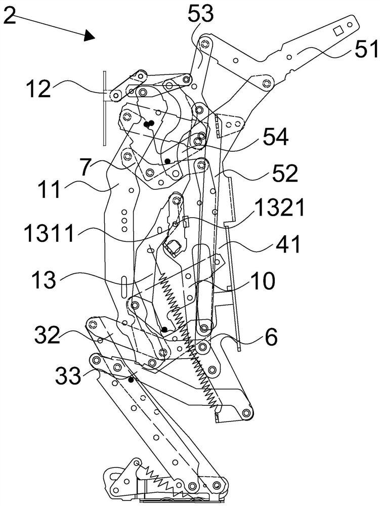
[0048] see Figure 1-15 , the present embodiment proposes a mechanical stretching device, including a base 1 and two mechanical...


PUM


Abstract

The invention discloses a mechanical stretching unit and a mechanical stretching device. The mechanical stretching unit comprises a footstool assembly, a cushion supporting assembly and a backrest assembly. The cushion supporting assembly comprises a seat mounting plate, and a first connecting rod mechanism is formed by a rear supporting connecting rod, a first stool collapse connecting rod, a second stool collapse connecting rod, a first transverse connecting rod, a first longitudinal connecting rod and the seat mounting plate and is used for driving the footstool assembly to move between a folding position and an unfolding position relative to the seat mounting plate; the backrest assembly comprises a backrest piece and a second transverse connecting rod, the second transverse connectingrod is arranged on one side of the first transverse connecting rod in parallel, and a second connecting rod mechanism is formed by arranging a front longitudinal connecting rod, a bottom connecting rod, a rear longitudinal connecting rod and the second transverse connecting rod and used for driving the backrest assembly to move between a leaning position and a reclining position. The footstool assembly and the backrest assembly are driven by the two sets of connecting rod mechanisms correspondingly, movement is stable, and the stretching process is coherent.

Description

technical field [0001] The present invention relates to the field of sports upholstered furniture for supporting the body of a user in a substantially sitting-stand position, and more particularly relates to a mechanical stretching unit and a mechanical stretching device. Background technique [0002] There are currently reclining seating units on the market that allow the user to extend the footrest or ottoman forward and recline the backrest relative to the seat. These existing seating units typically provide three basic positions: a standard non-recline stowed position; an extended position; and a reclined position. In the stowed position, the bottom is in a generally horizontal orientation and the backrest is arranged substantially upright. Additionally, if the seating unit includes a couch to which the mechanism is attached, the mechanism folds so that the couch does not extend. In the extended position, commonly referred to as the television ("TV") position, the couc...

Claims


Application Information

Patent Timeline
IPC IPC(8): A47C1/0355A47C20/10
CPCA47C1/0355A47C20/10
Inventor 陈永春施振杰李文才李立波
Owner UE FURNITURE CO LTD
Why Eureka
Try Eureka