Tumor resection device for oral and maxillofacial surgery
An oral maxillofacial and tumor technology, applied in the field of medical devices, can solve problems such as the inability to fix the patient's head, the limited working range of the imaging probe, and the difficulty in adjusting the detection probe.
- Summary
- Abstract
- Description
- Claims
- Application Information
AI Technical Summary
Problems solved by technology
Method used
Image
Examples
Embodiment 1
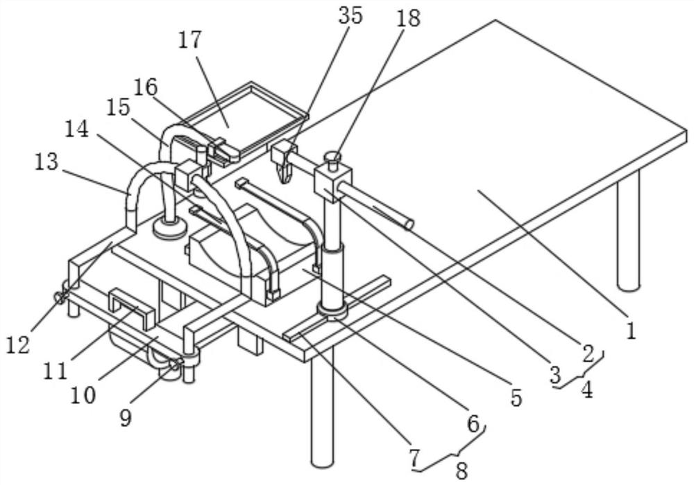
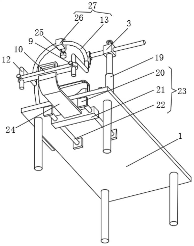
[0025] Embodiment 1: A tumor resection device for oral and maxillofacial surgery, including an operating bed 1, a lateral sliding mechanism 8 and a moving mechanism 23;
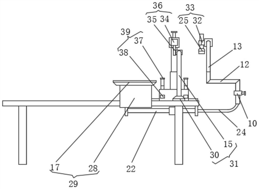
[0026] Operating bed 1: the operating bed 1 is provided with a dirt-holding mechanism 29, a twisting mechanism 31, and an arc-shaped pillow 5, the twisting mechanism 31 is equipped with a tumor resectator 16, and the arc-shaped pillow 5 is equipped with a strap 14, The other end of the strap 14 is detachably connected with the arc-shaped pillow 5 through the buckle mechanism 39, which can fix the patient's head and bring convenience to the operation. The input end of the tumor resecting device 16 and the output end of the external controller electrical connection;
[0027] Horizontal sliding mechanism 8: the electric telescopic rod 19 is installed on the horizontal sliding mechanism 8, and the telescopic end of the electric telescopic rod 19 is equipped with the longitudinal sliding mechanism 4, and the secon...
Embodiment 2
[0033] The difference between this embodiment and embodiment 1 is:
[0034] In this example,
[0035] The horizontal sliding mechanism 8 includes a movable block 6 and a slide rail 7, the slide rail 7 is arranged on the operating bed 1, the movable block 6 is assembled on the slide rail 7, and the electric telescopic rod 19 is arranged on the movable block 6; the longitudinal sliding mechanism 4 includes a second A sliding column 2 and a fixed block 3, the fixed block 3 is arranged on the telescopic end of the electric telescopic rod 19, the first sliding column 2 is arranged in the sliding hole of the fixed block 3, and the second fastening stud 18 is screwed on the fixed block 3 The clamping mechanism 36 includes a mounting block 34 and an electric clamp 35, the mounting block 34 is arranged on the end of the first sliding column 2, the electric clamp 35 is assembled on the lower surface of the mounting block 34, and the input end of the electric clamp 35 It is electrically...
Embodiment 3
[0038] The difference between this embodiment and embodiment 1 is:
[0039] In this example,
[0040]The moving mechanism 23 includes a mounting plate 20, a moving bar 21 and a second sliding column 22, two second sliding columns 22 are provided and are assembled in the sliding holes of the moving bar 21, and both ends of the second sliding column 22 are installed by The plate 20 is connected with the lower surface of the operating bed 1, and the connecting bar 24 is installed on the moving bar 21; the arc sliding mechanism 27 includes a slider 26 and an arc sliding column 13, and the two ends of the arc sliding column 13 are connected with two L-shaped The movable rod 12 is connected, and the arc-shaped sliding post 13 is arranged in the slide hole of the slide block 26; the detection mechanism 33 includes a detection probe 25 and a mounting ring 32, and the detection probe 25 is assembled in the inside of the mounting ring 32, and the mounting ring 32 and the sliding block ...
PUM
 Abstract
Description
Claims
Application Information
 - R&D
- Intellectual Property
- Life Sciences
- Materials
- Tech Scout
- Unparalleled Data Quality
- Higher Quality Content
- 60% Fewer Hallucinations
Browse by: Latest US Patents, China's latest patents, Technical Efficacy Thesaurus, Application Domain, Technology Topic, Popular Technical Reports.
© 2025 PatSnap. All rights reserved.Legal|Privacy policy|Modern Slavery Act Transparency Statement|Sitemap|About US| Contact US: help@patsnap.com


