Supercharge Your Innovation With Domain-Expert AI Agents!

Vertical bending machine

A bending machine and vertical technology, applied in the field of vertical bending machines and bending machines, can solve the problems of limited workshop operating table and space height, low work efficiency, etc., and achieve simple structure, high work efficiency, and highly operable effect

Pending Publication Date: 2020-09-22
周兆弟
View PDF0 Cites 0 Cited by
  • Summary
  • Abstract
  • Description
  • Claims
  • Application Information

AI Technical Summary

Problems solved by technology

[0004] The existing bending machine adopts vertical bending for flat steel mesh, which is limited by the height of the workshop operation table and space, resulting in low work efficiency. Therefore, the existing technology has defects and needs to be improved

Method used


Image

  • Vertical bending machine
  • Vertical bending machine
  • Vertical bending machine

Examples


Embodiment 1

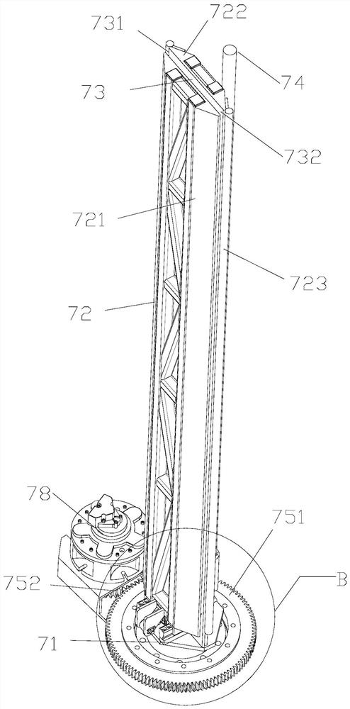
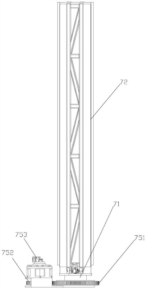
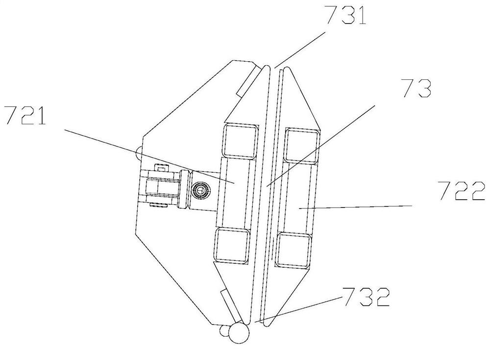
[0031] Embodiment one: if figure 1 , figure 2 , image 3 and Figure 4 As shown, this embodiment provides a vertical bending machine, including an upright clamping assembly 72 and a pressing assembly, wherein the clamping assembly 72 includes a clamping seat 71 , a fixed clamp fixed on the clamping seat 71 Part 722, and the movable clamping part 721 that is arranged on the clamping seat 71 and moves closer or farther away relative to the fixed clamping part 722, and forms between the fixed clamping part 722 and the movable clamping part 721 for the reinforcement mesh to pass through. The clamping channel 73 passes, and the vertical distance of the clamping channel 73 is higher than the height of the steel mesh sheet for bending. The fixed clamping part 722 and the movable clamping part 721 in the clamping assembly 72 all adopt a flat plate structure, and two flat plates placed vertically and parallel to each other form a clamping channel 73 between the flat plates, which c...

Embodiment 2

[0036] Embodiment 2: Compared with Embodiment 1, this embodiment provides a vertical bending machine with another structure, such as Figure 5 As shown, in the vertical bending machine of this embodiment, the driving assembly is used to drive the clamping assembly 72 to rotate, and the pressing assembly is fixed. The specific structure is that the clamping assembly 72 is vertically installed on the wobble plate 79, the wobble plate 79 is arranged on the upper surface of the driven gear 751, and the output shaft of the rotating motor 78 of the drive assembly drives the driven gear 751 to rotate, and then drives the wobble plate 79. And the clamping assembly 72 on it is rotated, and the pressing rod 74 is vertically arranged outside the clamping passage 73 of the clamping assembly 72 . Since the clamping assembly 72 clamps the steel mesh sheet, during its rotation, the steel mesh sheet extending out of the clamping channel 73 contacts the pressing bar 74 and is bent under the pr...

Embodiment 3

[0037] Embodiment 3: Compared with Embodiment 1, this embodiment provides a vertical bending machine with another structure, such as Figure 6 As shown, in the vertical bending machine of this embodiment, the driving component is used to drive the clamping component 72 and the pressing component to perform relative movement, so as to bend the steel mesh sheet clamped by the clamping component 72 . The specific structure is that the driving assembly includes a first driven gear 753 located under the pressing rod 74, a second driven gear 754 located under the clamping assembly 72, and the first driven gear 753 and the second driven gear. The driving gear 752 meshed with the gear 754 respectively, and the rotating motor 78 cooperating with the rotating shaft on the driving gear 752; Rod 74, the pressing rod 74 rotates with the first driven gear 753 along the outer circumference of the clamping assembly 72, the second driven gear 754 is provided with a swing plate 79, the clamping...


PUM


Abstract

The invention discloses a vertical bending machine used for bending a vertical steel bar mesh. A clamping assembly and a jacking assembly are included. The clamping assembly comprises a clamping baseand two clamping pieces vertically arranged on the clamping base. A clamping channel for a vertical steel bar mesh part to penetrate is arranged between the two clamping pieces. The jacking assembly is used for jacking the surface of the steel bar mesh extending out of the clamping channel so that the steel bar mesh can be bent with the plane deflecting angle of the clamping assembly relative to the jacking assembly as the bending angle. According to the vertical bending machine, the clamping assembly is used for clamping the steel bar mesh, and then the jacking assembly is used for conductingtransverse jacking and bending on the clamped steel bar mesh. The structure is simple, and compatibility is high. The vertical bending machine conducts vertical transverse bending on the steel bar mesh, is not limited by the workshop space and is high in work efficiency.

Description

【Technical field】 [0001] The invention relates to the technical field of bending machines, in particular to the technical field of vertical bending machines. 【Background technique】 [0002] Steel mesh is widely used in beam-column floors, roofs, walls, concrete pavements, bridge pavement, airport runways, tunnel linings, box culverts, dock floors, prefabricated components and other fields of industrial and civil buildings. [0003] Existing steel mesh sheets are produced as flat surfaces and are directly installed in building components. When encountering curved surfaces or angled surfaces, the steel mesh sheets are generally manually bent at the same time of installation to fit and connect with non-planar building components. This method requires high labor costs, and the quality of manual bending is low, and the bending error is large. In order to solve this problem, using a bending machine to bend the steel mesh will ensure the quality of the steel mesh and improve the s...

Claims


Application Information

Patent Timeline
IPC IPC(8): B21D11/12
CPCB21D11/125
Inventor 周兆弟
Owner 周兆弟
Features
  • R&D
  • Intellectual Property
  • Life Sciences
  • Materials
  • Tech Scout
  • Unparalleled Data Quality
  • Higher Quality Content
  • 60% Fewer Hallucinations
Learn More