Machine tool with optimised orientation of vibration dampers

A shock absorber, machine tool technology, applied in the field of machine tools, can solve problems with good results and the like

Active Publication Date: 2020-09-22
SIEMENS AG
View PDF13 Cites 0 Cited by
  • Summary
  • Abstract
  • Description
  • Claims
  • Application Information

AI Technical Summary

Problems solved by technology

In this case, known measures cannot always have good results

Method used


Image

  • Machine tool with optimised orientation of vibration dampers
  • Machine tool with optimised orientation of vibration dampers
  • Machine tool with optimised orientation of vibration dampers

Examples


Embodiment Construction

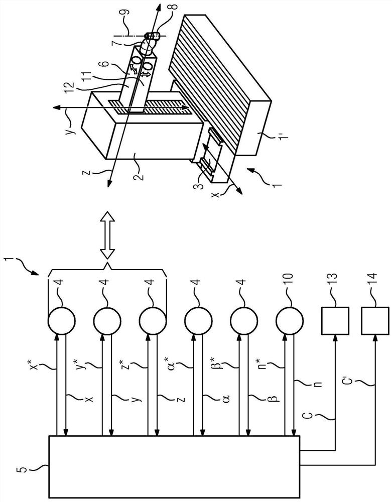
[0033] according to figure 1 , the machine tool has multiple machine elements. For example, a machine tool has a base body 1 as a machine element. On or at the base body 1 there is a workpiece table 1' as a further machine element, on which a workpiece (not shown) can be fastened. The column 2 forms another machine element. The column 2 is guided in a guide 3 of the base body 1 and is displaceable in a position-controlled manner by means of a drive 4 in the direction marked x. For this purpose, the control device 5 provides the corresponding drive 4 with a corresponding setpoint value x*.

[0034] Further guides can be arranged in the column 2 . This guide is not shown in the figures, but can be similar in design to the guide 3 . This other guide is referred to below as the outer guide. This designation is used to distinguish linguistically from another guide known as an inner guide.

[0035] The other guide, ie the inner guide, can be displaceable in a position-control...


PUM


Abstract

The invention relates to a machine tool with optimised orientation of vibration dampers. The machine tool includes a first machine element and a second machine element; the first machine element is guided in a guide device of the second machine element, and the first machine element moves in the guide device of the second machine element in a positionally controlled manner in the travel directionby means of a drive of the machine tool. The first and second side faces of the first machine element run parallel to the travel direction and are oriented at a right angle to each other. The machinetool has a first vibration damper and a second vibration damper, by means of which vibrations of the first machine element in the respective vibration direction can be damped. The vibration directionis oriented perpendicular to the movement direction. The first damper and / or the second damper are / is oriented in such a way that the direction of vibration of the vibrations that can be damped separately by means of the first or second damper is oriented neither parallel to the first end face nor parallel to the second end face.

Description

technical field [0001] The invention is based on a machine tool, [0002] - wherein the machine tool has at least one first machine element and a second machine element, [0003] - wherein the first machine element is guided in a guide of the second machine element, and the first machine element is displaceable in the direction of movement in a position-controlled manner by means of a drive of the machine tool in the guide of the second machine element, [0004] - wherein the first machine element has a first end face and a second end face, [0005] - wherein the first end face and the second end face extend parallel to the direction of movement and are oriented perpendicular to each other, [0006] - wherein the machine tool has a first vibration damper and a second vibration damper, by means of the first vibration damper and the second vibration damper, respectively, the vibrations of the first machine element occurring in the corresponding vibration direction can be dampe...

Claims


Application Information

Patent Timeline
IPC IPC(8): B23Q11/00F16F15/02
CPCB23Q11/0032F16F15/02B23Q2220/006B23Q1/621
Inventor 约亨·布雷特施奈德乌韦·拉德拉埃尔玛·谢菲尔斯托尔斯滕·舒尔
Owner SIEMENS AG
Why Eureka
Try Eureka