Mounting tool for front-engine front-wheel drive (FF) engine and suspension frame

A technology for installing tooling and engines, applied in manufacturing tools, hand-held tools, etc., can solve the problems of worn screw grooves, deformation of raised parts, affecting the efficiency of engine assembly, and achieve the effect of easily locking screws and avoiding scratches

Active Publication Date: 2020-09-22
CHONGQING COLLEGE OF ELECTRONICS ENG
View PDF6 Cites 0 Cited by
  • Summary
  • Abstract
  • Description
  • Claims
  • Application Information

AI Technical Summary

Problems solved by technology

[0004] Although this solves the problem that the assembly holes of the suspension frame and the assembly holes of the engine cannot be aligned, it is necessary to tighten the screws in the first assembly hole twice, which also affects the assembly efficiency of the engine to a certain extent; In the actual installation, it will be found that during the process of tightening the screw with a tool similar to a screwdriver, the tool will wear the notch of the screw, resulting in deformation of the protrusion between adjacent notches

Method used


Image

  • Mounting tool for front-engine front-wheel drive (FF) engine and suspension frame
  • Mounting tool for front-engine front-wheel drive (FF) engine and suspension frame
  • Mounting tool for front-engine front-wheel drive (FF) engine and suspension frame

Examples


Embodiment 1

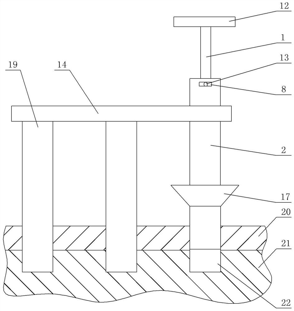
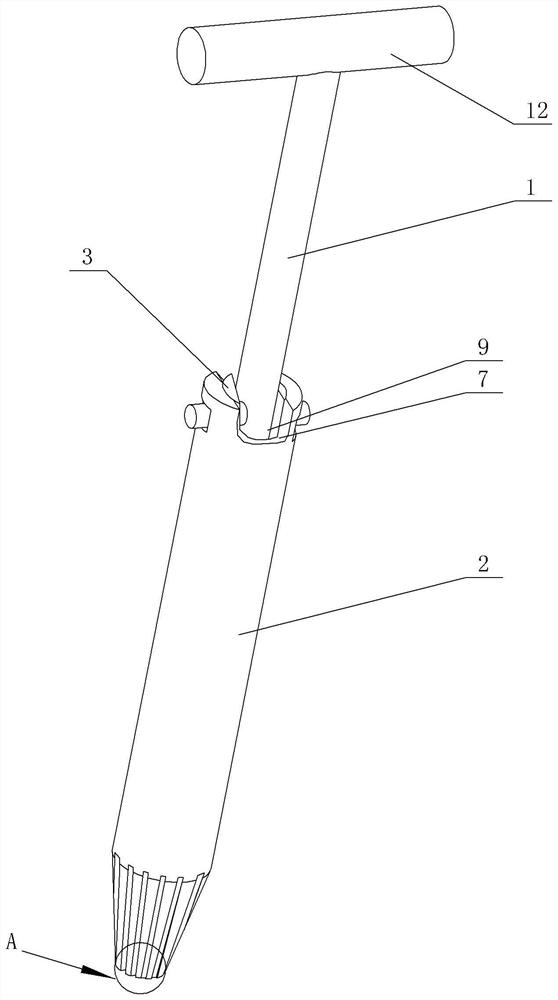
[0028] Embodiment one is basically as attached Figure 1-6 Shown: as figure 1 The shown front front drive engine 21 and suspension frame 20 installation tooling include positioning plate 14, grip bar 1, twist pipe 2 and as figure 2 , 4 As shown in the screw rod 3, two positioning rods 19 are welded on the positioning plate 14, holes are opened on the positioning plate 14, the screwing tube 2 is slidingly connected with the side wall of the hole, and the screwing tube 2 and the two positioning rods 19 on the same vertical plane.

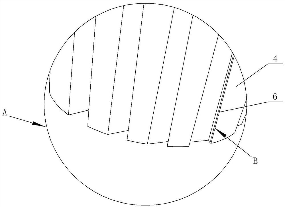
[0029] like figure 2 As shown, the lower end of the screw tube 2 is tapered; image 3 As shown, the lower end of the screw tube 2 is distributed with screw teeth 4 along the circumferential direction, such as Figure 4 As shown, there is a cavity 5 in the screw tooth 4, such as image 3 As shown, there is an opening 6 at the transition position (position B shown) between the tooth surface of the screwing tooth 4 and the end surface of the scre...

Embodiment 2

[0035] On the basis of Example 1, as Figure 4 As shown, the external rotation of the screw tube 2 is provided with an outer sleeve 15, and the lower end of the outer sleeve 15 is fixed with a magnet 16, and the magnet 16 arranged at the lower end of the outer sleeve 15 is adsorbed with the suspension frame 20, so that the screwing can be improved. Tube 2 Stability. The diameter of the screw rod 3 is greater than the diameter of the upper end of the card body 10, and the upper end of the clamp tooth 11 is welded to the lower end surface of the screw rod 3, which is conducive to improving the firmness of the clamp tooth 11; the clamp tooth 11 is made of cast iron, which can ensure The strength of the locking tooth 11 is large enough. In addition, the connecting rod 13 is coated with a graphite powder layer, which can ensure that the connecting rod 13 slides smoothly in the chute 8 .


PUM


Abstract

The invention relates to the field of mounting of engines and suspension frames, in particular to a mounting tool for a front-engine front-wheel drive (FF) engine and a suspension frame. The mountingtool comprises a positioning plate, a holding rod, a screwing pipe and a screwing rod, wherein two positioning rods are fixed on the positioning plate; the screwing pipe is arranged on the positioningplate in a sliding manner; screwing teeth are circumferentially distributed at the lower end of the screwing pipe; a cavity is formed in each screwing tooth; an opening is formed in a transition position between a tooth surface and an end surface of each screwing tooth, and communicates with the inside of the screwing pipe through the corresponding cavity; a notch is formed at the upper end of the screwing pipe; chutes are formed on the side walls of the upper end of the screwing pipe; the screwing rod is rotationally arranged in the screwing pipe; a groove is formed at the upper end of the screwing rod; a clamping body is fixed at the lower end of the screwing rod; clamping teeth are circumferentially distributed on the clamping body and located in the corresponding cavities; and a connecting rod is fixed on the holding rod, rotationally connected with the screwing rod, and arranged in the chutes in a sliding manner. The mounting tool adopting the technical scheme has the advantagesthat assembly holes of the engine and the suspension frame can be aligned, and notch abrasion can be reduced.

Description

technical field [0001] The invention relates to the field of installation of engines and suspension frames, in particular to a tool for installing front and front drive engines and suspension frames. Background technique [0002] When installing the front-mounted front-drive engine (hereinafter referred to as the engine) on the suspension frame, since the engine and the suspension frame each have three assembly holes on the same straight line, the assembly of the suspension frame will occur during installation. The phenomenon that the hole and the assembly hole of the engine cannot be aligned has greatly affected the production cycle and caused serious economic losses. [0003] In order to solve this problem, the current processing method is to pre-tighten the screws through one assembly hole of the suspension frame and one assembly hole of the engine, and then pass the screws through the remaining two assembly holes of the suspension frame and the engine Assemble, and fina...

Claims


Application Information

Patent Timeline
Patent Type & Authority Applications(China)
IPC IPC(8): B25B27/14
CPCB25B27/14
Inventor 刘红玉张传华倪艳姝蒋维刘人源
Owner CHONGQING COLLEGE OF ELECTRONICS ENG
Why Eureka
Try Eureka