Linkage-transmission rotating and lifting mechanism

A technology of rotating lifting and connecting rod transmission, applied in the direction of lifting devices, etc., can solve problems such as damage to rotating parts and failure to meet the functional requirements of innovative products, and achieve the effects of improving stability, improving operating experience, and convenient operation

Pending Publication Date: 2020-09-22
DONGGUAN ZHONGKE GUANTENG TECH CO LTD
View PDF0 Cites 0 Cited by
  • Summary
  • Abstract
  • Description
  • Claims
  • Application Information

AI Technical Summary

Problems solved by technology

[0004] The risk of damage to the rotating parts is easy to occur during the user's use. The existing products can no longer meet the functional requirements of innovative products. Therefore, it is necessary to provide a connecting rod transmission rotating lifting mechanism that can rotate and lift simultaneously.

Method used


Image

  • Linkage-transmission rotating and lifting mechanism
  • Linkage-transmission rotating and lifting mechanism
  • Linkage-transmission rotating and lifting mechanism

Examples


Embodiment Construction

[0037] In order to make the object, technical solution and advantages of the present invention more clear, the present invention will be further described in detail below in conjunction with the examples, but the protection scope of the present invention is not limited to the following specific examples.

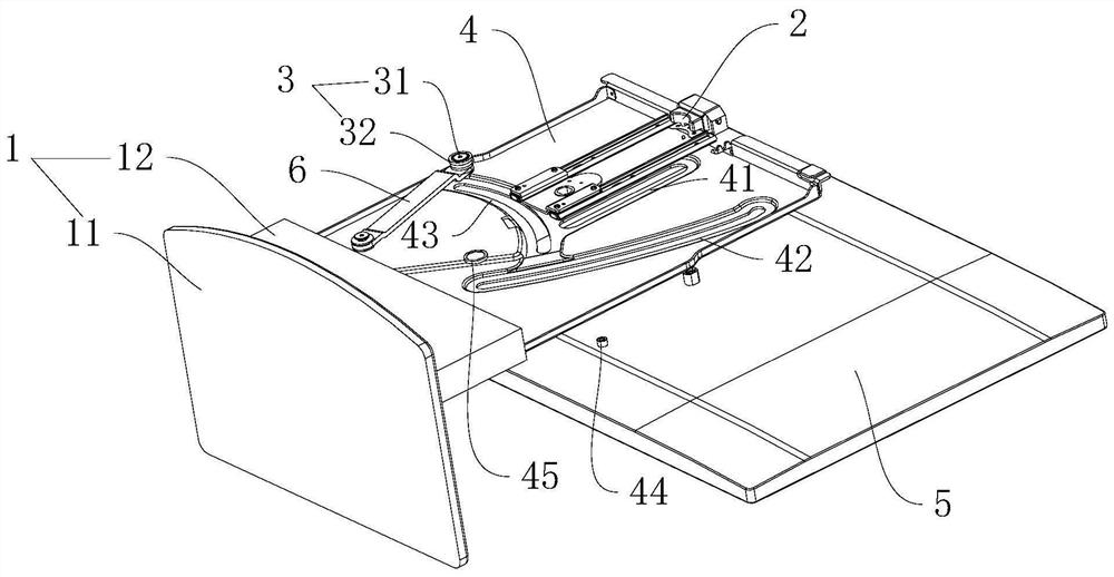
[0038] refer to figure 1 , the present embodiment discloses a connecting rod 6 transmission rotation lifting mechanism, including a fixed base 1 , a fixed plate 4 , a rotating member 5 , a lifting assembly 2 , a rotating assembly 3 and a connecting rod 6 .

[0039] refer to figure 1 , the fixing base 1 includes a base plate 11 and a support plate 12 vertically fixed to the base plate 11 , and the fixing plate 4 is fixedly connected to the top of the support plate 12 . The support plate 12 is respectively provided with a lifting slideway 41, a rotating slideway 42 and a balancing slideway 43 that run through the supporting plate 12, wherein the rotating slideway 42 and the b...


PUM


Abstract

The invention discloses a linkage-transmission rotating and lifting mechanism. According to the technical scheme adopted by the invention, the linkage-transmission rotating and lifting mechanism comprises a fixed plate, a lifting assembly and a rotating assembly, and further comprises a rotary part, wherein both the lifting assembly and the rotating assembly are arranged on the fixed plate; the lifting assembly comprises a lifting shaft; the rotating assembly comprises a rotary shaft; both the lifting shaft and the rotary shaft are fixedly connected on the rotary part; a lifting slide path anda rotary slide path are arranged on the fixed plate; the lifting shaft is movably arranged in the lifting slide path; the rotary shaft is movably arranged in the rotary slide path; a connecting rod is arranged on the fixed plate; one end of the connecting rod is rotatably connected to the fixed plate; and one end, away from the joint with the fixed plate, of the connecting rod is connected to therotary part. The linkage-transmission rotating and lifting mechanism achieves the purposes of rotating and lifting simultaneously.

Description

technical field [0001] The invention relates to the field of rotary lifting mechanisms, in particular to a connecting rod transmission rotary lifting mechanism. Background technique [0002] The rotary lifting mechanism refers to a mechanical structure that has both lifting and rotating functions. [0003] Most of the existing rotating and lifting mechanisms are separate and independent mechanisms for lifting and rotating functions. When in use, the rotating member needs to be raised to the highest point first, and then the rotating member can be tilted back to realize the function of rotating. [0004] The risk of damage to the rotating parts is likely to occur during the user's use, and the existing products can no longer meet the functional requirements of innovative products. Therefore, it is necessary to provide a connecting rod transmission rotating and lifting mechanism that can rotate and lift simultaneously. Contents of the invention [0005] The object of the pr...

Claims


Application Information

Patent Timeline
Patent Type & Authority Applications(China)
IPC IPC(8): B66F11/00B66F13/00
CPCB66F11/00B66F13/00
Inventor 张庆军
Owner DONGGUAN ZHONGKE GUANTENG TECH CO LTD
Why Eureka
Try Eureka