
Double-gear type linkage speed change device

A speed change device and linkage technology, applied in the direction of gear transmission, transmission, transmission control, etc., can solve the problem of inconvenient double-gear linkage transmission

Active Publication Date: 2020-09-22
绍兴柯桥皓悦纺织科技有限公司
View PDF5 Cites 1 Cited by
  • Summary
  • Abstract
  • Description
  • Claims
  • Application Information

AI Technical Summary

Problems solved by technology

[0002] The speed change device can help the mechanical speed change work, solve the inconvenience of traditional mechanical speed change, and at the same time, it can be conveniently installed and connected, so that the speed change device can adapt to more mechanical environments, achieve the purpose of saving time and effort, facilitate maintenance work, and ensure product quality The quality of the transmission, through the setting of the transmission device, can easily adjust the speed, help to adjust the overall transmission ratio, and facilitate the speed control. However, the current transmission device has the following problems, and it is not convenient to carry out double-gear linkage transmission at the inner end. The phenomenon will cause some inconvenience and needs to be improved

Method used


Image

  • Double-gear type linkage speed change device
  • Double-gear type linkage speed change device
  • Double-gear type linkage speed change device

Examples


Embodiment Construction

[0020] The following will clearly and completely describe the technical solutions in the embodiments of the present invention with reference to the accompanying drawings in the embodiments of the present invention. Obviously, the described embodiments are only some, not all, embodiments of the present invention. Based on the embodiments of the present invention, all other embodiments obtained by persons of ordinary skill in the art without making creative efforts belong to the protection scope of the present invention.

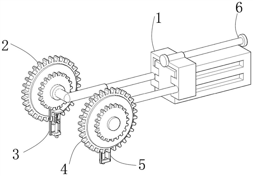
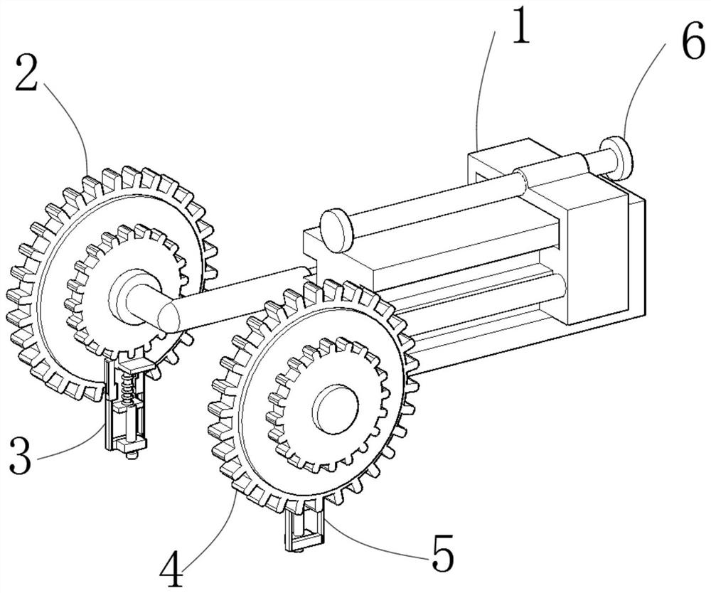
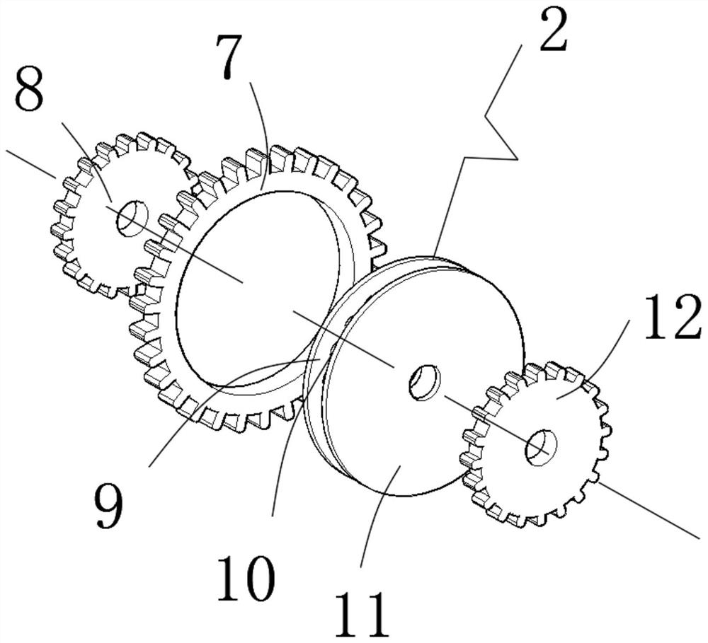
[0021] see Figure 1-5, the present invention provides a technical solution: a double-tooth-type linkage transmission device, including a transmission device main body 1, a displacement device 6 is provided at the bottom of the inner end of the transmission device main body 1, and one side of the front end of the displacement device 6 is rotatably connected to a The other side of the front end of the first speed change toothed disc 2 and the displacement devic...


PUM


Abstract

The invention discloses a double-gear type linkage speed change device. The device comprises a speed change device main body, a displacement device is arranged at the bottom of the inner end of the speed change device main body, a first speed change fluted disc is rotationally connected to one side of the front end of the displacement device, a second speed change fluted disc is rotationally connected to the other side of the front end of the displacement device, a first regulation and control device is slidably connected to the lower end of the first speed change fluted disc, a second regulation and control device is slidably connected to the lower end of the second speed change fluted disc, the first speed change fluted disc comprises a first ring gear, a second ring gear, a first contact disc, balls, a second contact disc and a third ring gear, the first ring gear is arranged in the center of the inner end of the first speed change fluted disc, the inner end of the first ring gear is rotationally connected with the balls, and one sides of the balls are rotationally connected with the first contact disc. According to the double-gear type linkage speed change device, through the arrangement of the first regulation and control device and the second regulation and control device, the purpose of inner-end double-gear type linkage speed change is achieved.

Description

technical field [0001] The invention relates to the technical field of mechanical equipment, in particular to a double-tooth linkage transmission device. Background technique [0002] The speed change device can help the mechanical speed change work, solve the inconvenience of traditional mechanical speed change, and at the same time, it can be conveniently installed and connected, so that the speed change device can adapt to more mechanical environments, achieve the purpose of saving time and effort, facilitate maintenance work, and ensure product quality The quality of the transmission, through the setting of the transmission device, can easily adjust the speed, help to adjust the overall transmission ratio, and facilitate the speed control. However, the current transmission device has the following problems, and it is not convenient to carry out double-gear linkage transmission at the inner end. The phenomenon will cause some inconvenience and needs to be improved. Cont...

Claims


Application Information

Patent Timeline
Patent Type & Authority Applications(China)
IPC IPC(8): F16H3/087F16H59/02
CPCF16H3/087F16H59/02F16H2003/0818
Inventor 李斌
Owner 绍兴柯桥皓悦纺织科技有限公司
Learn More