
Railway tunnel lighting power supply system

A technology of tunnel lighting and power supply system, applied in the field of tunnel lighting, can solve problems such as tunnel lighting energy consumption, and achieve the effect of enriching visual experience and expanding publicity.

Active Publication Date: 2020-09-22
CHINA ROAD & BRIDGE
View PDF5 Cites 0 Cited by
  • Summary
  • Abstract
  • Description
  • Claims
  • Application Information

AI Technical Summary

Problems solved by technology

[0005] Another object of the present invention is to provide a power supply system for railway tunnel lighting, which can convert the kinetic energy generated by the high-speed moving train and the wind generated during the running process into electricity for tunnel lighting at medium and high speeds in the tunnel, which solves the problem of tunnel lighting. The problem of energy consumption for tunnel lighting, and the power generated by high-speed EMUs will not be affected by weather changes, and the energy is infinite and environmentally friendly

Method used


Image

  • Railway tunnel lighting power supply system
  • Railway tunnel lighting power supply system
  • Railway tunnel lighting power supply system

Examples


Embodiment Construction

[0042] The present invention will be further described in detail below in conjunction with the accompanying drawings, so that those skilled in the art can implement it with reference to the description.

[0043] It should be understood that terms such as "having", "comprising" and "including" as used herein do not entail the presence or addition of one or more other elements or combinations thereof.

[0044]It should be noted that the experimental methods described in the following embodiments, unless otherwise specified, are conventional methods, and the reagents and materials, if not otherwise specified, can be obtained from commercial sources; in the description of the present invention, It should be noted that, unless otherwise clearly stipulated and limited, the terms "installation", "connection" and "arrangement" should be interpreted in a broad sense, for example, it can be fixedly connected, arranged, or detachably connected, arranged, or Connect and set in one piece. ...


PUM


Abstract

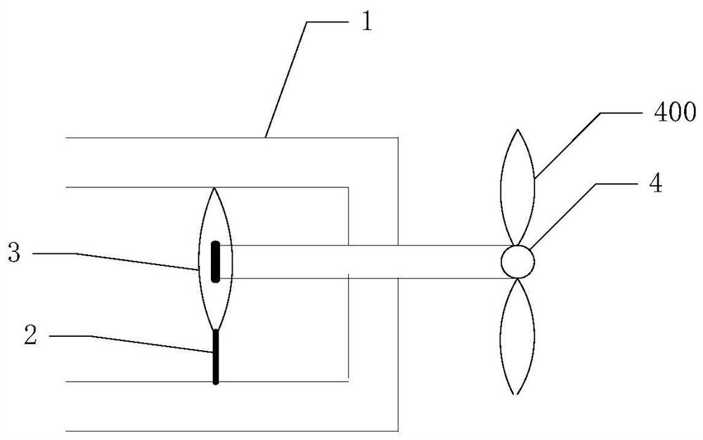
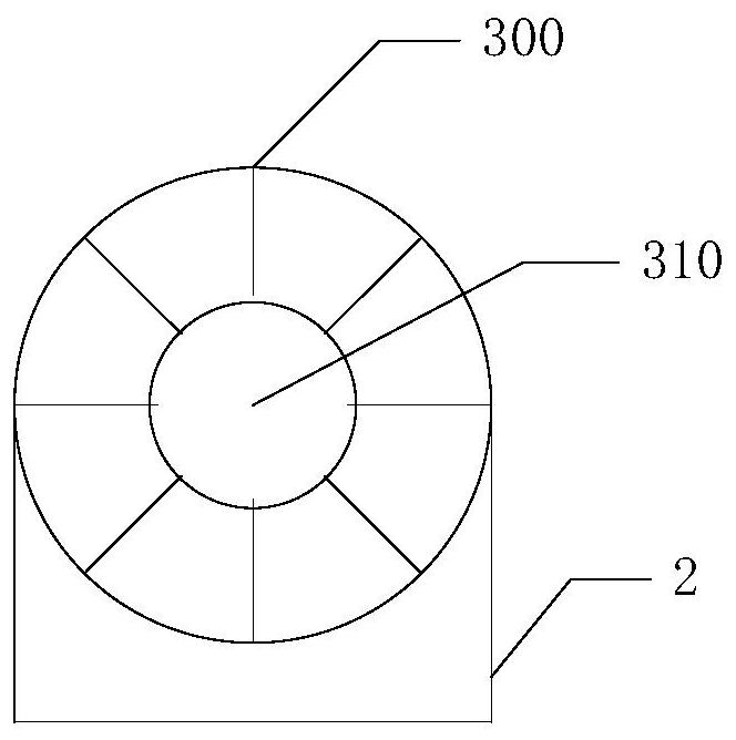
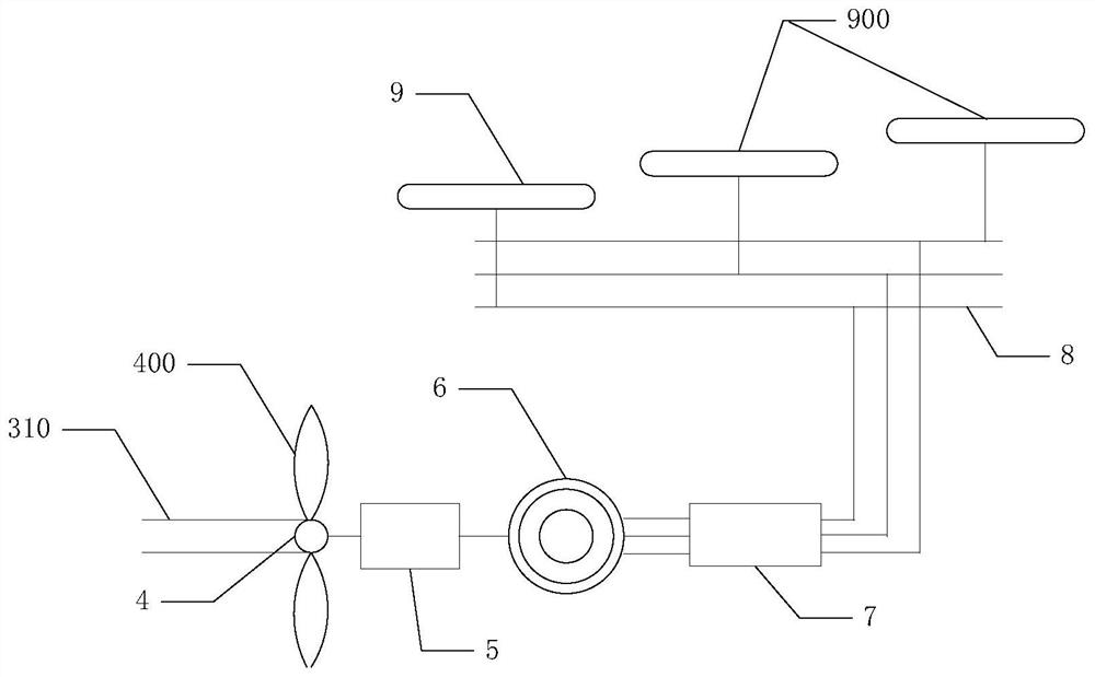
The invention discloses a railway tunnel lighting power supply system. The system comprises a plurality of power receiving mechanisms which are arranged on a rail in a railway tunnel at intervals, wherein each power receiving mechanism comprises a supporting device and a rotating device, each rotating device comprises a vertical part and a horizontal part, the vertical parts are supported in railgrooves through the supporting devices and make contact with the upper surfaces in the grooves, and the horizontal parts penetrate through the rail and extend out of the rail; a power mechanism whichis provided with a plurality of rotating blades, wherein the rotating blades are driven by the rotation of the rotating device to rotate; a power transmission mechanism which is used for acceleratingthe rotating blades and transmitting the power generated by the power mechanism at the same time; a power generation mechanism which converts power of the power transmission mechanism into electric energy; an electric power mechanism and a power grid for transmitting the alternating current output by the electric power mechanism; and an illumination mechanism which is used for receiving the alternating current to illuminate the tunnel. Kinetic energy generated by a bullet train running at a high speed and wind generated in the running process can be converted into electricity for tunnel lighting, and the problem of tunnel lighting energy consumption is solved.

Description

technical field [0001] The invention relates to the technical field of tunnel lighting. More specifically, the present invention relates to a railway tunnel lighting power supply system. Background technique [0002] With the continuous growth of the country's comprehensive national strength, high-speed EMUs have extended to almost every city, railways have been developed to many mountainous areas, and the number of tunnels is also increasing rapidly. It is bound to produce a large amount of power consumption. Although in recent years there have been "green, low-carbon, and environmentally friendly" researches on tunnel lighting, such as the introduction of wind power generators in tunnels, and the use of optical fibers to bring sunlight into tunnels for lighting, these are still incomplete and are more affected by the weather environment. Big. [0003] The maximum running speed of high-speed EMU trains can reach 400km / h, and the continuous running speed is 350km / h. Due t...

Claims


Application Information

Patent Timeline
Patent Type & Authority Applications(China)
IPC IPC(8): H02S10/10H02S10/12H02S40/30F03D9/00F03D9/11H02K7/18H02J7/00H02J7/14H02J7/32H02J7/35H02J3/38F21S9/03F21S9/04F21V23/04F21V33/00F21Y115/10
CPCF03D9/007F21S9/032F21S9/043F21V23/04F21V33/0052F03D9/11F21Y2115/10H02J3/381H02J7/0047H02J7/0068H02J7/14H02J7/1423H02J7/32H02J7/35H02K7/1807H02K7/183H02S10/10H02S10/12H02S40/30H02J7/00302H02J7/00306H02J7/143H02J2207/40H02J2300/28Y02E10/50Y02E10/72Y02E10/76Y02E70/30
Inventor 何保炳张欣樊泽民郑甲佳
Owner CHINA ROAD & BRIDGE
Learn More