Bearing pressing machine

A bearing and transmission shaft technology, applied in the field of bearing presses, can solve problems such as inconvenient operation, low safety, and low efficiency

Inactive Publication Date: 2020-09-25
刘茂椿
View PDF7 Cites 3 Cited by
  • Summary
  • Abstract
  • Description
  • Claims
  • Application Information

AI Technical Summary

Problems solved by technology

[0004] In order to overcome the shortcomings of low efficiency, inconvenient operation and low safety caused by manual pressing of bearings, the technical problem is to provide a bearing pressing machine capable of fixing workpieces and bearings, automatically pressing bearings, saving time and effort, and being simple to operate

Method used


Image

  • Bearing pressing machine
  • Bearing pressing machine
  • Bearing pressing machine

Examples


Embodiment 1

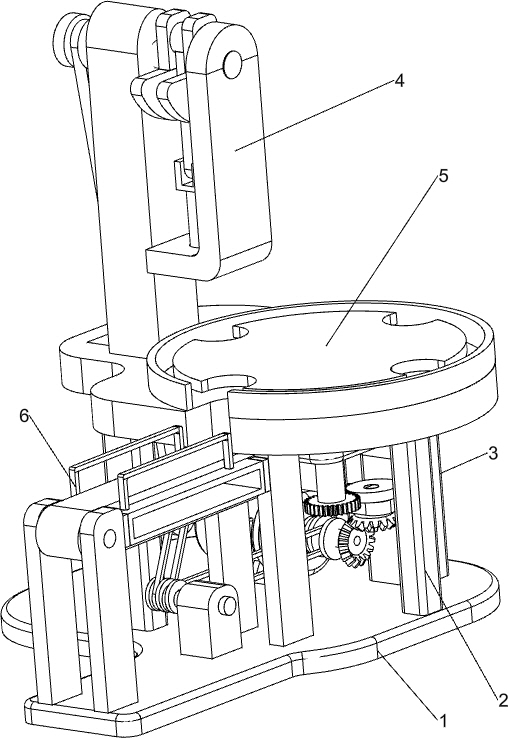
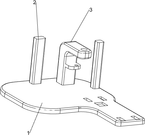
[0023] A bearing press machine such as Figure 1-2 As shown, it includes a base 1, a pillar 2, a first support frame 3, a pressing mechanism 4 and a rotating mechanism 5. The middle part of the front and rear sides of the top of the base 1 and the middle part of the right side are provided with a pillar 2, and the top right rear part of the base 1 is It is connected with the first supporting frame 3 by welding, a pressing mechanism 4 is connected between the top of the pillar 2 and the top of the base 1 , and a rotating mechanism 5 is connected between the first supporting frame 3 and the pressing mechanism 4 .

[0024] When the bearing needs to be pressed, people place the bearing collection frame on the front side of the top of the base 1, people first clamp the bearing to be pressed on the parts of the rotating mechanism 5, and then start the parts of the pressing mechanism 4, and the parts of the pressing mechanism 4 rotate one side Drive the parts of the rotating mechanis...

Embodiment 2

[0026] On the basis of Example 1, such as Figure 3-5 As shown, the pressing mechanism 4 includes a motor 41, a first transmission shaft 42, a workbench 43, a first pulley 44, a second support frame 45, a first flat belt 46, a second pulley 47, a second transmission shaft 48, a centrifugal Block 49, the third transmission shaft 410, pressing rod 411, the fourth transmission shaft 412 and the fixed block 413, the top left rear part of the base 1 is provided with a motor 41, the motor 41 is located between the pillars 2 on the left side, the motor 41 The output shaft on the left side is connected with the first transmission shaft 42, the first pulley 44 is connected with the left side of the first transmission shaft 42, the workbench 43 is connected between the tops of the pillars 2, and the top of the workbench 43 is connected with the rotating mechanism 5, and the working The left side of the table 43 has a square hole, the middle part of the workbench 43 has a second circular...

Embodiment 3

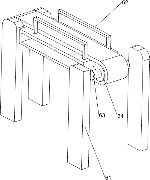
[0031] On the basis of Example 2, such as Figure 6-7 As shown, it also includes a blanking mechanism 6. The blanking mechanism 6 includes a third support frame 61, an inner frame 62, a seventh transmission shaft 63, a transmission sleeve 64, a transmission belt 65, a third pulley 66, a second flat Belt 67, fixed support block 68, eighth transmission shaft 69, double-groove pulley 610, fourth pulley 611 and the third flat belt 612, the left and right sides of base 1 top front side and middle side are all provided with a third support frame 61 , the inner frame 62 is arranged between the upper part of the third support frame 61, and the seventh transmission shaft 63 is rotatably connected between the third support frame 61 on the left and right sides, and the transmission shaft sleeve 64 is arranged on the seventh transmission shaft 63 A transmission belt 65 is connected between the transmission shaft sleeves 64, a third pulley 66 is provided on the left side of the seventh tra...


PUM


Abstract

The invention relates to a pressing machine, in particular to a bearing pressing machine. According to the bearing pressing machine, workpieces and bearings can be fixed, the bearings can be automatically pressed, the time and labor are saved, and operation is easy. The bearing pressing machine comprises a base, supporting columns, a first supporting frame, a pressing mechanism, a rotating mechanism and a discharging mechanism; the supporting columns are arranged in the middles of the front side and the rear side and the middle of the right side of the top of the base correspondingly; the first supporting frame is arranged on the rear part of the right side of the top of the base; the pressing mechanism is connected between the tops of the supporting columns and the top of the base; and the rotating mechanism is connected between the first supporting frame and the pressing mechanism, and the discharging mechanism is arranged on the front right side of the base. When needing to press the bearings, people place the bearings needing to be pressed into a part of the rotating mechanism, the pressing mechanism is started, under cooperation of the rotating mechanism, the bearings are pressed by the pressing mechanism, when pressing of the bearings is completed, the bearings fall into the discharging mechanism, and people can take out the bearings orderly.

Description

technical field [0001] The invention relates to a mechanical pressing machine, in particular to a bearing pressing machine. Background technique [0002] Bearing is an important part of contemporary mechanical equipment. Its main function is to support the mechanical rotation, reduce the friction coefficient during its movement, and ensure its rotation accuracy. The existing bearing pressing method is that people hold the workpiece and the bearing manually. Positioning, and then holding the tool to knock the workpiece into the bearing. Repeating this operation for a long time will easily cause people's arms to ache, and it is easy to hit people's hands. The safety is low and the operation is inconvenient. [0003] Since the manual pressing of the bearings above brings a lot of inconvenience to the workers, in order to solve these inconveniences, a bearing pressing machine that can fix the workpiece and the bearing, automatically press the bearing, save time and effort, and i...

Claims


Application Information

Patent Timeline
Patent Type & Authority Applications(China)
IPC IPC(8): B23P19/00B23P19/02
CPCB23P19/008B23P19/02
Inventor 刘茂椿
Owner 刘茂椿
Why Eureka
Try Eureka