Assembly error ultrasonic detection method and waveguide ultrasonic assisted assembly method

An ultrasonic detection and assembly error technology, applied in the direction of using ultrasonic/sonic/infrasonic waves, re-radiation of sound waves, radio wave measurement systems, etc., can solve the problems of rework assembly, long assembly time, unstable quality, etc., and achieve high-precision assembly. , the effect of improving assembly quality and assembly efficiency

Active Publication Date: 2021-06-22
广州多浦乐电子科技股份有限公司
View PDF0 Cites 0 Cited by
  • Summary
  • Abstract
  • Description
  • Claims
  • Application Information

AI Technical Summary

Problems solved by technology

Even if the human eye can observe, the alignment accuracy of the waveguide cannot be guaranteed without feedback data; resulting in long assembly time, poor accuracy, assembly quality varies from person to person, often reworked assembly, and the quality is unstable; it is difficult to be efficient and fast , One-time assembly with guaranteed quality and quantity

Method used


Image

  • Assembly error ultrasonic detection method and waveguide ultrasonic assisted assembly method
  • Assembly error ultrasonic detection method and waveguide ultrasonic assisted assembly method
  • Assembly error ultrasonic detection method and waveguide ultrasonic assisted assembly method

Examples


Embodiment 1

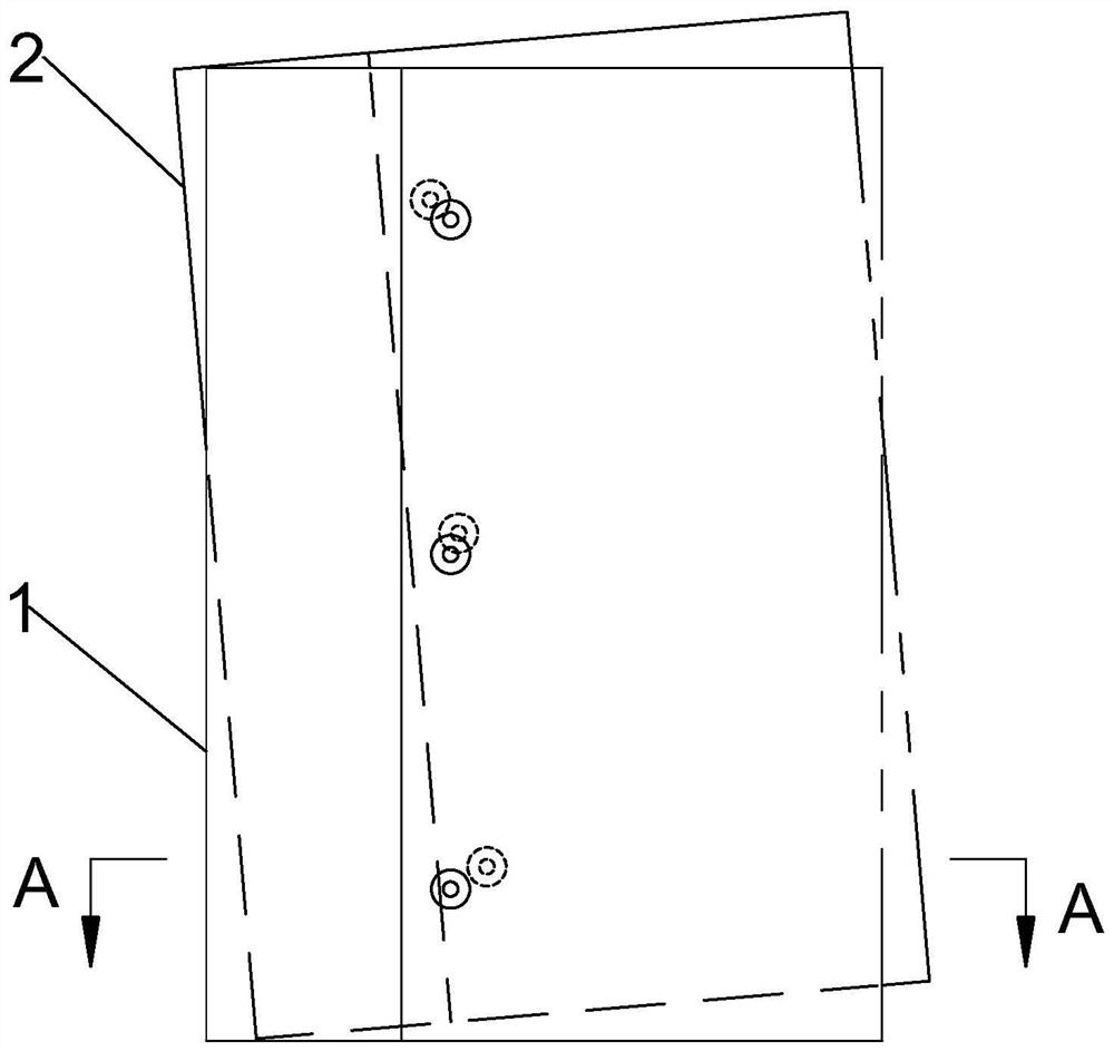
[0050] In the assembly error ultrasonic detection method of this embodiment, if at least one assembly alignment surface is respectively provided on the two assembly workpieces, and the two assembly alignment surfaces are relative to the distance between the two assembly workpieces after the two assembly workpieces are assembled in place. The first assembly mating surface 5 is symmetrically arranged; then two ultrasonic detection point groups can be symmetrically arranged on both sides of the first assembly mating surface 5, and the two ultrasonic detection point groups are respectively located on two assembly workpieces. The detection point group includes at least two first ultrasonic detection points 6 arranged at intervals, and all the first ultrasonic detection points 6 belonging to the same ultrasonic detection point group are at the same distance from the first assembly mating surface 5 and belong to the same ultrasonic detection point All the first ultrasonic testing poin...

Embodiment 2

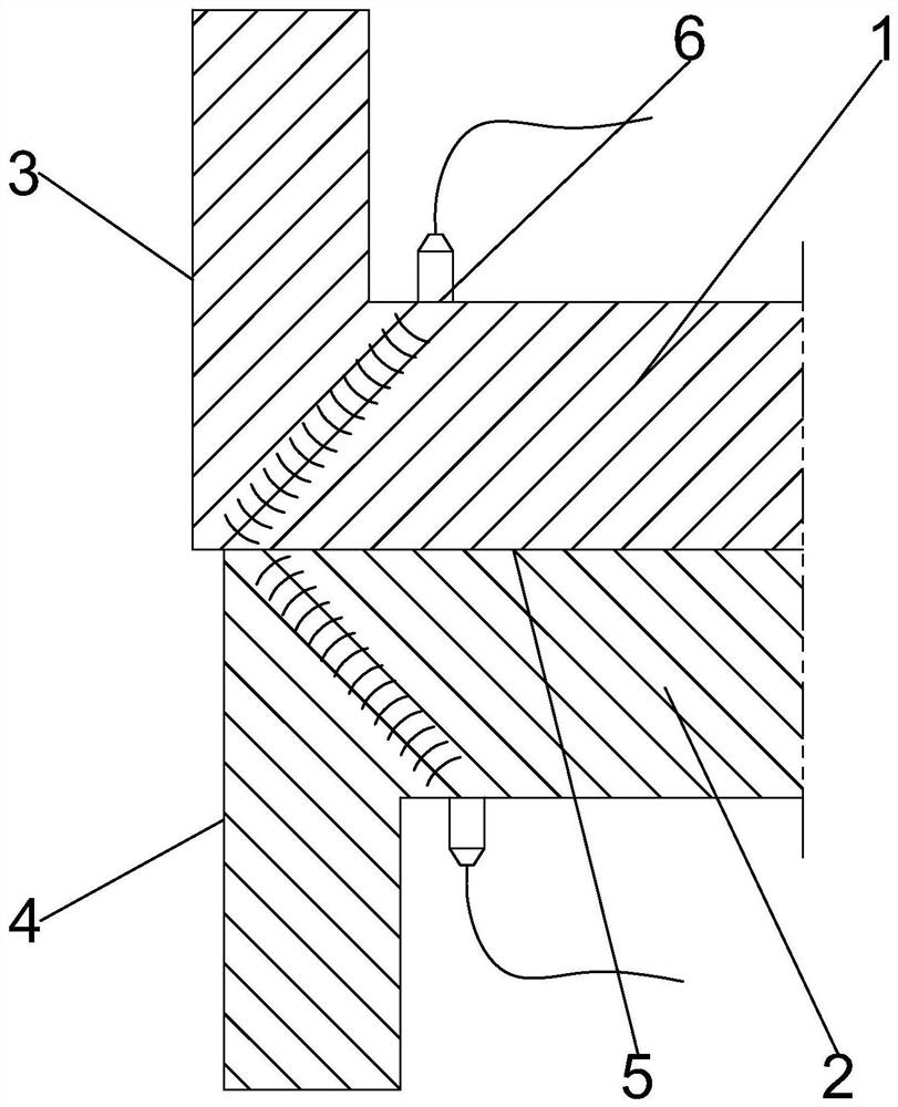
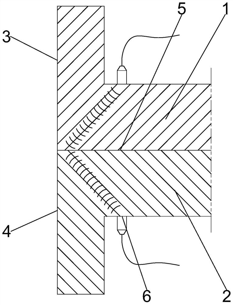
[0072] In the assembly error ultrasonic detection method of this embodiment, if two assembly workpieces are respectively provided with at least two assembly alignment surfaces, and the two assembly alignment surfaces on the same assembly workpiece are arranged in axisymmetric manner, and when the two assembly alignment surfaces After the two assembly workpieces are assembled in place, the axisymmetric planes of the two assembly alignment surfaces respectively arranged on the two assembly workpieces are coplanar, and the second assembly mating surface 13 between the two assembly workpieces is perpendicular to the axisymmetric plane, Then, two ultrasonic testing point groups can be respectively symmetrically arranged on both sides of the axisymmetric plane, and the two ultrasonic testing point groups are located on the same assembly workpiece, and each ultrasonic testing point group includes at least two second For the ultrasonic testing point 14, all the ultrasonic testing point...

Embodiment 3

[0089] In the waveguide ultrasonic-assisted assembly method of this embodiment, a central through hole 15 is provided in the waveguide. The cross section of the central through hole 15 is square and includes a first assembly alignment surface group and a second assembly alignment surface group perpendicular to each other. Both the first assembly alignment face group and the second assembly alignment face group include two assembly alignment faces parallel to each other. Specifically, the first assembly alignment surface group in this embodiment includes the seventh assembly alignment surface 16 and the eighth assembly alignment surface 17 , and the second assembly alignment surface group includes the ninth assembly alignment surface 18 and the tenth assembly alignment surface 19 .


PUM


Abstract

The invention discloses an assembly error ultrasonic detection method, by setting two ultrasonic detection point groups, and setting at least two ultrasonic detection points at intervals in each ultrasonic detection point group, thus, using the same ultrasonic detection point group The energy amplitude of the ultrasonic echo signals at different ultrasonic detection points can directly determine whether there is a rotation error between two assembly workpieces, and the average value of the energy amplitudes of the ultrasonic echo signals of the two ultrasonic detection point groups In this case, it can be judged whether there is a translation error between two assembled workpieces, that is, the assembly error ultrasonic detection method of the present invention can accurately detect the type and direction of the assembly error, and can be used to guide the operator to complete the high-precision assembly work.

Description

technical field [0001] The invention belongs to the technical field of ultrasonic non-destructive testing, in particular to an ultrasonic detection method for assembly errors and an ultrasonic-assisted assembly method for waveguides. Background technique [0002] Magnetron radar uses a waveguide to transmit radar waves, and the waveguide path is composed of a series of waveguide components. This series of waveguide components may come from different manufacturers, and the processing accuracy and assembly accuracy standards of each manufacturer may not be completely consistent. Therefore, in order to be compatible with components supplied by different manufacturers, the gap between the locking and positioning of the components is usually A certain amount of assembly margin is left. It is precisely because of the existence of the assembly margin that it is difficult to equip the waveguide. During assembly, it is required that the inner tube channel of the waveguide assembly ...

Claims


Application Information

Patent Timeline
Patent Type & Authority Patents(China)
IPC IPC(8): B23P19/00G01S15/06G01S7/539G01B17/00
CPCB23P19/00G01B17/00G01S7/539G01S15/06
Inventor 蔡庆生骆琦韩松陆宇
Owner 广州多浦乐电子科技股份有限公司
Why Eureka
Try Eureka