A fringe image transformation tube mounting tool and mounting method

A technology for changing image tubes and racking, which is applied in the direction of image conversion/image enlargement tubes, electrode devices and related components, screen tubes, etc., which can solve the problems of large mounting errors, reduce material consumption, improve efficiency and yield , saving time and manpower

Active Publication Date: 2015-09-02
XI'AN INST OF OPTICS & FINE MECHANICS - CHINESE ACAD OF SCI
View PDF4 Cites 0 Cited by
  • Summary
  • Abstract
  • Description
  • Claims
  • Application Information

AI Technical Summary

Problems solved by technology

[0010] In order to solve the technical problem of large installation errors when adopting the current striped image transformation tube assembly method for striped tube assembly, the invention provides a high-precision mounting tool and a mounting method for the striped image transformation tube

Method used


Image

  • A fringe image transformation tube mounting tool and mounting method
  • A fringe image transformation tube mounting tool and mounting method
  • A fringe image transformation tube mounting tool and mounting method

Examples


Embodiment Construction

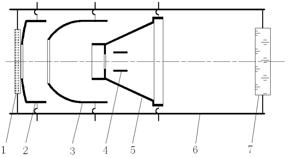
[0037] figure 1 Shown is the structural diagram of the stripe image transformation tube, including the tube casing 6, and the cathode 1, the grid 2, the focusing electrode 3, the deflection electrode 4, the anode 5, and the fluorescent screen 7 are welded in sequence in the axial direction from one end of the tube casing to the other end.

[0038] Aiming at the striped image transformation tube with this structure, the present invention provides a striped image transformation tube mounting tool, its structure is as follows: Figure 4 As shown, it includes a pair of round tubes 9 formed by interlocking, end caps 91 arranged at both ends of the round tube 9, and a first positioning device and a second positioning device coaxially arranged with the round tube. There is an annular step 92 equal to the number of electrodes in the image changing tube. The axial position of the annular step 92 is determined according to the position of each electrode in the image changing tube. The i...


PUM


Abstract

The invention relates to a stripe image converter tube racking tool, which comprises a pair of circular tube formed by mutually buckled, a first end cover and a second end cover arranged on two ends of the circular tube, and a first locating device and a second locating device arranged coaxial to the circular tube, wherein annular steps with the number being equal to the number of electrodes in an image converter tube are arranged on an inner wall of the circular tube; axial positions of the annular steps are determined according to positions of the electrodes in the image converter tube; and inner holes of the annular steps are matched with the matched electrodes. According to the racking tool, the position accuracy including axial deviation, radial deviation, coaxiality and the like in a stripe tube racking process can be improved; an uncontrollable process link and manual operation are reduced, so that the consistency of racking is improved; and the efficiency for manufacturing stripe tubes and the yield are improved.

Description

technical field [0001] The method of the invention relates to an ultrafast diagnostic technology device, in particular to the assembly of a stripe image transformation tube, which is a core component of a stripe camera. Background technique [0002] Ultrafast phenomena (duration less than 1 μs) widely appear in natural or scientific and technological research. For example, the photosynthesis process of plants, the electrical pulse generated by ultra-large-scale polar circuits, the carrier lifetime of semiconductor materials, the ultrafast photoexcited state relaxation process in laser materials, the molecular dynamics process of chemical reactions, the fluorescence of biological materials The emission, the duration of the ultrashort laser pulse generated by the laser, and the physical process of the interaction between strong light and matter are mostly in the range of picoseconds to femtoseconds, or even attoseconds. Therefore, the study of ultrafast phenomena is of great ...

Claims


Application Information

Patent Timeline
Patent Type & Authority Patents(China)
IPC IPC(8): H01J31/50H01J29/46H01J29/04H01J29/82
Inventor 卢裕田进寿王俊锋张铁徐向晏王超曹希斌段东平
Owner XI'AN INST OF OPTICS & FINE MECHANICS - CHINESE ACAD OF SCI
Why Eureka
Try Eureka