Prefabricated underground diaphragm wall, segmented connector structure and construction method

A technology of underground continuous wall and joint structure, which is applied in basic structure engineering, sheet pile wall, construction, etc., can solve the problems of easy leakage of water, bulging, and complicated procedures at the joints of the ground connecting wall, so as to simplify the on-site construction process. , Improve waterproof performance and ensure the effect of construction quality

Pending Publication Date: 2020-09-25
CHINA RAILWAY SIYUAN SURVEY & DESIGN GRP
View PDF0 Cites 3 Cited by
  • Summary
  • Abstract
  • Description
  • Claims
  • Application Information

AI Technical Summary

Problems solved by technology

[0002] Underground diaphragm wall is a commonly used enclosure structure in foundation pit engineering. It often needs to be poured in advance after troughing and lowering the steel cage. The traditional cast-in-place method has the following disadvantages: 1. It is difficult to guarantee the construction quality of the underground diaphragm wall in field pouring. There will be situations such as exposed ribs and bulges; 2. The cast-in-place construction is laborious and laborious. It is necessary to hang the reinforcement cage first and then pour the concrete, which is a complicated process; 3. When the geological conditions are poor, the joints of the ground wall are also prone to water leakage. Affect the overall safety of the foundation pit
Prefabricated underground diaphragm wall is a good solution for this, but due to the depth and weight of underground diaphragm wall, the hoisting equipment is difficult to meet the requirements, which has become a factor restricting the use of prefabricated diaphragm wall

Method used


Image

  • Prefabricated underground diaphragm wall, segmented connector structure and construction method
  • Prefabricated underground diaphragm wall, segmented connector structure and construction method
  • Prefabricated underground diaphragm wall, segmented connector structure and construction method

Examples


Embodiment Construction

[0032] The following will clearly and completely describe the technical solutions in the embodiments of the present invention with reference to the accompanying drawings in the embodiments of the present invention. Obviously, the described embodiments are only some, not all, embodiments of the present invention. Based on the embodiments of the present invention, all other embodiments obtained by persons of ordinary skill in the art without making creative efforts belong to the protection scope of the present invention.

[0033] In describing the present invention, it is to be understood that the terms "center", "upper", "lower", "front", "rear", "left", "right", "vertical", "horizontal", The orientations or positional relationships indicated by "top", "bottom", "inner", "outer", etc. are based on the orientations or positional relationships shown in the drawings, and are only for the convenience of describing the present invention and simplifying the description, rather than in...


PUM


Abstract

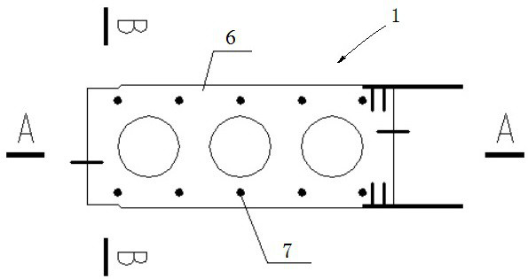
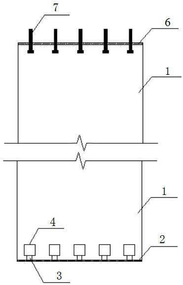
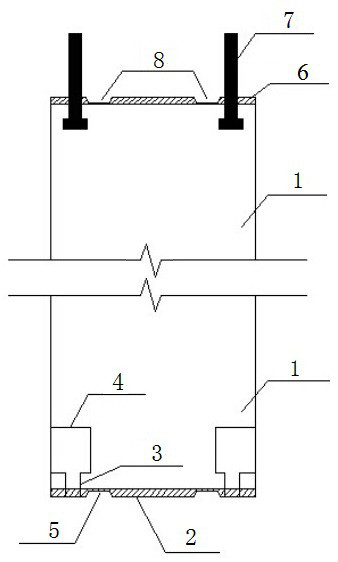
The invention belongs to the technical field of foundation pit engineering and particularly relates to a prefabricated underground diaphragm wall. A first embedded steel plate and a second embedded steel plate are laid at the two ends of a prefabricated underground diaphragm wall body correspondingly. Multiple bolt holes are reserved in one end of the prefabricated underground diagram wall body, multiple bolts are embedded in the other end of the prefabricated underground diagram wall body, and one ends of the bolts penetrate the second embedded steel plate. Multiple hand holes are formed in the side wall of the prefabricated underground diagram wall body, and the multiple bolt holes communicate with the multiple hand holes. The invention further provides a segmented connector structure ofthe prefabricated underground diagram wall and a construction method of the segmented connector structure of the prefabricated underground diagram wall. The construction method includes the steps that the above prefabricated underground diaphragm wall is adopted as the previous-constructed prefabricated underground diaphragm wall and the posterior-constructed prefabricated underground diaphragm wall; the bolts on the previous-constructed prefabricated underground diaphragm wall penetrate the corresponding bolt holes of the posterior-constructed prefabricated underground diaphragm wall and then stretch into the corresponding hand holes to be fixed through nuts. A prefabricated assembly manner is adopted, the construction quality can be ensured, the field construction processes are simplified, and the construction efficiency is improved.

Description

technical field [0001] The invention belongs to the technical field of foundation pit engineering, and in particular relates to a prefabricated underground continuous wall and section joint structure and construction method. Background technique [0002] The underground diaphragm wall is a commonly used enclosure structure in foundation pit engineering. It often needs to be poured in advance after the reinforcement cage is lowered into grooves. The traditional cast-in-place method has the following disadvantages: 1. It is difficult to guarantee the construction quality of the underground diaphragm wall in the field pouring. There will be situations such as exposed ribs and bulges; 2. The cast-in-place construction is laborious and laborious. It is necessary to hang the reinforcement cage first and then pour the concrete, which is a complicated process; 3. When the geological conditions are poor, the joints of the ground wall are also prone to water leakage. affect the overal...

Claims


Application Information

Patent Timeline
Patent Type & Authority Applications(China)
IPC IPC(8): E02D5/10E02D5/12E02D5/14
CPCE02D5/10E02D5/12E02D5/14
Inventor 赵星张海涛李文彪王金龙吕延豪蔡兴瑞游龙飞郑凯孙雪兵范可佳艾婷
Owner CHINA RAILWAY SIYUAN SURVEY & DESIGN GRP
Why Eureka
Try Eureka