Concrete uniaxial tension load and test device and use method thereof

A technology for testing devices and concrete test blocks, which is applied in the direction of measuring devices, instruments, scientific instruments, etc., can solve the problems of complicated test operation process and difficult centering of concrete test pieces, and achieve simplified test devices, effective continuous load, and simple structure Effect

Active Publication Date: 2020-09-25
YANGZHOU UNIV
View PDF31 Cites 2 Cited by
  • Summary
  • Abstract
  • Description
  • Claims
  • Application Information

AI Technical Summary

Problems solved by technology

[0005] Aiming at the problems of difficult centering of concrete specimens and relatively complicated test operation process when using traditional concrete tensile test devices, th

Method used


Image

  • Concrete uniaxial tension load and test device and use method thereof
  • Concrete uniaxial tension load and test device and use method thereof
  • Concrete uniaxial tension load and test device and use method thereof

Examples


Embodiment 1

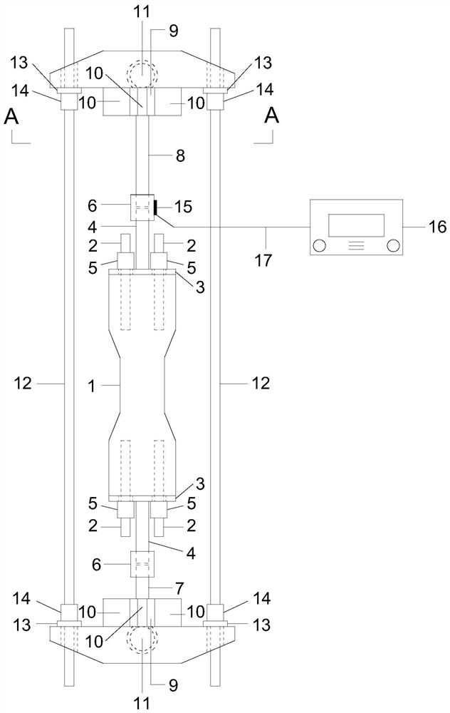
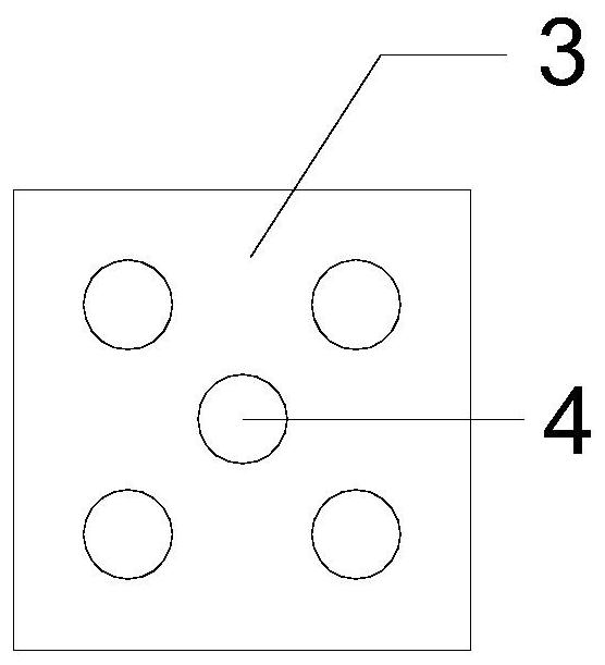
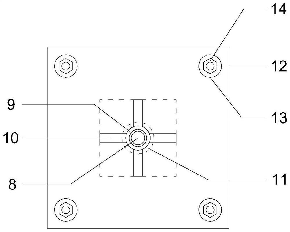
[0037] Such as figure 1 As shown, a concrete uniaxial tensile load test device includes a concrete test block 1, a finish-rolled threaded steel bar 2, a square anchor plate 3, a prestressed finish-rolled threaded steel bar specification-4, a finished-rolled nut specification-5, a connection Sleeve 6, ordinary connecting rod 7, extended connecting rod 8, reinforced round steel pipe 9, rectangular stiffened steel plate 10, ball hinge 11, prestressed finish-rolled threaded steel bar specification 2 12, steel washer 13, finish-rolled nut specification 2 14, Strain gauge 15, resistance strain gauge 16, connecting wire 17. The concrete test block 1 (120mm×120mm×400mm) is a non-standard type. Considering the effect of reducing the stress effect at the end and ensuring that the tensile failure occurs in the middle part, the area of ​​the middle part of the test piece is reduced, and a self-made steel mold is used. To complete the pouring and molding of the test piece, remove the form...

Embodiment 2

[0053] Such as Figure 5 As shown, a concrete uniaxial tension test device takes out the load-bearing device in the erosive environment simulation device, and adds a square steel plate 18 and a through-core puller 19 on the basis of the load-bearing device. Two new square steel plates 18 are added, one of which is placed between the upper part of the connecting sleeve 6 and the rectangular stiffener steel plate 10 to support the upper through-hole drawing instrument 19, and the lower steel washer 13 and finish rolling The nut specification two 14 is fixed, and the other one is arranged on the top of the through-heart drawing instrument 19 to withstand the rectangular stiffened rib steel plate 10; the rectangular stiffened rib steel plate 10 is arranged as a rectangle to facilitate the support of the square steel plate 18 below; The core-through drawing instrument 19 is arranged on the square steel plate 18 for applying tension; as Figure 6 As shown, the steel washer 13 and t...


PUM


Abstract

The invention discloses a concrete uniaxial tension load holding and testing device and a using method thereof. An independent load sensor does not need to be adopted, and the concrete uniaxial tension load holding and testing device also serves as a load sensor through the method that a connecting sleeve internally provided with the threads and the outer smooth circle is pasted with a resistancestrain gauge, so the testing device is simplified, and the cost problem that a large number of load sensors need to be occupied for long-term load holding is solved. Axial tension is applied to the concrete test block by simultaneously rotating the four second finish rolling nuts close to one side of an upper spherical hinge. Load is obtained by using the connecting sleeve pasted with the strain gauges as a load sensor, and fine adjustment of the load is realized by slightly rotating the second specification of the finish rolling nut. For a concrete uniaxial tension testing device, a square steel plate and a straight-through drawing instrument are additionally arranged on the basis of a load holding device. According to the invention, a concrete uniaxial tension holding load and a testingdevice are combined into one, so the operation is simple, and a stable and effective continuous load can be provided.

Description

technical field [0001] The invention belongs to the field of civil engineering, and in particular relates to a concrete uniaxial tensile load and testing device and a use method thereof, and is especially suitable for studying the durability test of a concrete uniaxial tensile test piece under the coupled action of load and erosive environment. Background technique [0002] As we all know, concrete is one of the most widely used building materials in current engineering structures, and its compressive strength is its most prominent feature, while less attention has been paid to its tensile strength. Therefore, in modern structures, concrete is mainly used to bear the compressive strength, and the tensile strength of concrete is generally only 1 / 17~1 / 8 of the compressive strength, and a small load can reach the tensile strength of concrete, so in In structural design, the tensile strength of concrete is usually neglected and the tensile strength of the structure is borne by s...

Claims


Application Information

Patent Timeline
IPC IPC(8): G01N3/06G01N3/02
CPCG01N3/06G01N3/02G01N2203/0003G01N2203/0017G01N2203/0252G01N2203/0676G01N2203/024Y02E10/50
Inventor 葛文杰王冠严卫华王仪高培琦仇胜伟曹大富陆伟刚
Owner YANGZHOU UNIV
Why Eureka
Try Eureka