Check patentability & draft patents in minutes with Patsnap Eureka AI!

Detection method for detecting target object using double detectors and double detectors

A technology of double detectors and detection methods, which is applied in the direction of electromagnetic wave detection, special electric/magnetic detection, instruments, etc. during transportation

Active Publication Date: 2022-04-12
亚历山大·曼内斯基
View PDF7 Cites 0 Cited by
  • Summary
  • Abstract
  • Description
  • Claims
  • Application Information

AI Technical Summary

Problems solved by technology

The detector therefore does not scan the ground

Method used


Image

  • Detection method for detecting target object using double detectors and double detectors
  • Detection method for detecting target object using double detectors and double detectors
  • Detection method for detecting target object using double detectors and double detectors

Examples


Embodiment Construction

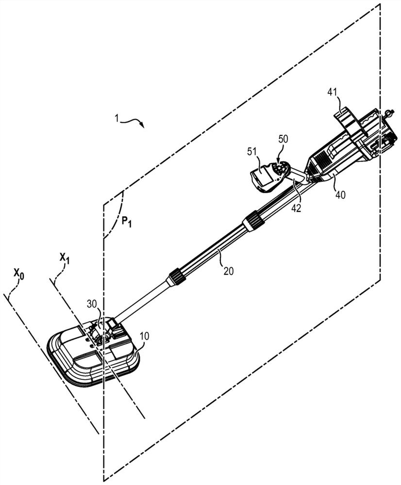
[0044] The double detector 1 according to the invention comprises a detection head 10 fixed to a handle 20 by means of a mechanical linkage 30 .

[0045] The detection head 10 corresponds to a portion intended to approach the ground in order to detect a target product. For this purpose it includes:

[0046] -Platform 11

[0047] - an inductive sensor fixed to the platform 11 and comprising a transmitting coil 12 and a receiving coil 13 distinct from each other, and

[0048] - Another sensor, preferably a ground penetrating radar.

[0049]The transmitting coil 12 and the receiving coil 13 are homopolar windings. In a manner known per se, they are configured to transmit and receive waves with a frequency between 300 Hz and 180 kHz. They each form a loop and are shaped such that the loop of the transmitting coil 12 at least partially covers the loop of the receiving coil 13 so as to form the coupling region 14 . This configuration allows obtaining an inductive sensor with mi...


PUM


Abstract

The invention relates to a double detector comprising a detection head (10) having: - a platform (11); and - an inductive sensor mounted on said platform (11) and comprising A transmitter coil (12) and a separate receiver coil (13), the transmitter coil (12) and receiver coil (13) each forming a loop, the loop of the transmitter coil (12) at least partially overlapping the receiving The loop of the detector coil (13) so as to form the coupling area (14), which defines the first axis (X 1 ) is elongated in the first longitudinal direction, the arm (20) is perpendicular to the plane (P 1 ), and the first axis (X of the coupling region (14) 1 ) transverse to the plane (P 1 )stretch.

Description

technical field [0001] The present invention relates to the field of detection of target objects, and more particularly to detection of explosives such as land mines buried in the ground. Background technique [0002] For the detection of explosives, it is known to use dual technology detectors ("dual detectors") comprising a detection head housing an inductive sensor and a ground penetrating radar, as far as these technologies are complementary in terms of the type of material detected (metal vs. Inductive sensor vs. difference in dielectric constant of the material and relative position of the radar). [0003] However, in use, the Applicant has noticed that the ground is not neutral from an electromagnetic point of view and thus may interfere with the coupling between the windings. In addition, the ground is seldom uniformly magnetic, so that during an operator scanning the ground with the detector, the detected signal may only change due to the presence of metal debris o...

Claims


Application Information

Patent Timeline
Patent Type & Authority Patents(China)
IPC IPC(8): H04B5/00
CPCG01V3/10G01V3/12G01V3/16G01V3/105H04B5/73H04B5/24G01V3/15H04B5/00G01S13/878G01S13/885G01S13/887
Inventor 亚历山大·曼内斯基
Owner 亚历山大·曼内斯基
Features
  • R&D
  • Intellectual Property
  • Life Sciences
  • Materials
  • Tech Scout
  • Unparalleled Data Quality
  • Higher Quality Content
  • 60% Fewer Hallucinations
Learn More