Tire

A technology for tires and crowns, which is applied to tire parts, tire treads/tread patterns, transportation and packaging, etc. It can solve the problems of low rigidity of pattern blocks and falling blocks, so as to improve snow performance and snow drainage Effect

Pending Publication Date: 2020-09-29
SUMITOMO RUBBER IND LTD
View PDF1 Cites 0 Cited by
  • Summary
  • Abstract
  • Description
  • Claims
  • Application Information

AI Technical Summary

Problems solved by technology

[0004] However, in the tire of Patent Document 1, the rigidity of the blocks divided by the zigzag-shaped main grooves and the lateral grooves is low, resulting in heel-toe wear that is locally worn in the tire circumferential direction, and local block defects, that is, dropped blocks. case, so there is room for improvement in uneven wear resistance

Method used


Image

  • Tire
  • Tire
  • Tire

Examples


Embodiment Construction

[0023] Hereinafter, one embodiment of the present invention will be described in detail based on the drawings.

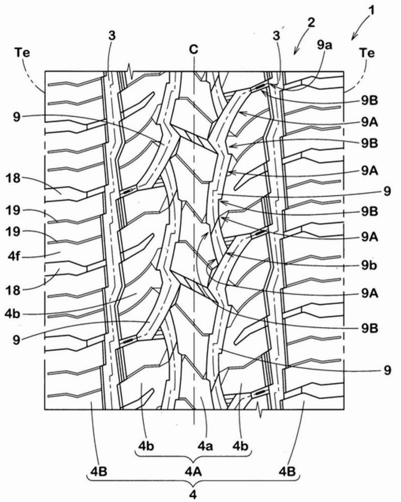
[0024] figure 1 It is a developed view showing the tread portion 2 of the tire 1 of the present embodiment. Such as figure 1 As shown, the tire 1 of the present embodiment is suitable as a pneumatic tire having a tread portion 2 suitable for running on snowy roads.

[0025] The tire 1 may be a pneumatic tire for running on uneven roads such as muddy ground, for example, other than snowy roads. In addition, the tire 1 is not limited to a pneumatic tire, and may be a non-pneumatic tire that does not fill the inside of the tire 1 with pressurized air, for example.

[0026] A plurality of circumferential grooves 3 extending in the tire circumferential direction and a plurality of land portions 4 defined by the circumferential grooves 3 are formed in the tread portion 2 of the present embodiment. For example, one circumferential groove 3 is formed between the tire eq...


PUM


Abstract

The present invention provides a tire having both on-snow performance and uneven wear resistance. A crown land portion (4A) is formed on the tread portion (2) by a pair of circumferential grooves (3)extending in the tire circumferential direction. The crown land portion (4A) is provided with a plurality of crown grooves (9) extending from the pair of circumferential grooves (3) toward the insideof the crown land portion (4A). The crown grooves (9) do not traverse the tire equator (C) and extend continuously in the tire circumferential direction as a whole from the plurality of crown grooves(9). The crown land portion (4A) includes a center portion (4a) defined between crown grooves (9) adjacent to each other in the tire axial direction. The center part (4a) is provided with a center sipe (6) extending between crown grooves (9) adjacent to each other in the tire axial direction, and a center cutout part (7) recessed inward in the tire axial direction from the crown grooves (9). The center sipe (6) has end portions (6a) on both sides in the tire axial direction. At least one of the end sections (6a) communicates with the central cutout section (7).

Description

technical field [0001] The present invention relates to a tire having a tread portion excellent in on-snow performance. Background technique [0002] Conventionally, tires having a tread portion suitable for running on snowy roads are known. For example, the following Patent Document 1 proposes a pneumatic tire having a tread portion divided into blocks by a plurality of main grooves extending continuously in a zigzag shape in the tire circumferential direction and a plurality of lateral grooves connecting the main grooves. . The tire of Patent Document 1 exhibits high traction when running on snowy roads, and thus has excellent snow performance. [0003] Patent Document 1: Japanese Patent Laid-Open No. 2017-128268 [0004] However, in the tire of Patent Document 1, the rigidity of the blocks divided by the zigzag-shaped main grooves and the lateral grooves is low, resulting in heel-toe wear that is locally worn in the tire circumferential direction, and local block defec...

Claims


Application Information

Patent Timeline
IPC IPC(8): B60C11/03B60C11/12
CPCB60C11/03B60C11/1236B60C2011/0339B60C2011/0341Y02T10/86
Inventor 谷田健
Owner SUMITOMO RUBBER IND LTD
Why Eureka
Try Eureka