
Equipment and method for testing ultimate bearing capacity of concrete-filled steel tube axial compression short column

A technology of concrete-filled steel tubes and ultimate bearing capacity, which is applied in the direction of applying stable tension/compression to test the strength of materials, measuring devices, instruments, etc. , to achieve the effect of easy testing and easy transportation

Active Publication Date: 2020-09-29
PUTIAN UNIV
View PDF8 Cites 4 Cited by
  • Summary
  • Abstract
  • Description
  • Claims
  • Application Information

AI Technical Summary

Problems solved by technology

When measuring the ultimate bearing capacity of conventional CFST, there is no special equipment to fix the CFST, which makes the CFST easy to shake during the long-term test process, which affects the measured data, and when the CFST is stamped. CFST is often tested by placing it on a stamping machine, which is not easy to transport and often makes testing difficult on construction sites

Method used


Image

  • Equipment and method for testing ultimate bearing capacity of concrete-filled steel tube axial compression short column
  • Equipment and method for testing ultimate bearing capacity of concrete-filled steel tube axial compression short column
  • Equipment and method for testing ultimate bearing capacity of concrete-filled steel tube axial compression short column

Examples


Embodiment Construction

[0038] The technical solutions of the present invention will be further described below in conjunction with the accompanying drawings and through specific implementation methods.

[0039]Wherein, the accompanying drawings are only for illustrative purposes, showing only schematic diagrams, rather than physical drawings, and should not be construed as limitations on this patent; in order to better illustrate the embodiments of the present invention, some parts of the accompanying drawings will be omitted, Enlarged or reduced, does not represent actual product size.

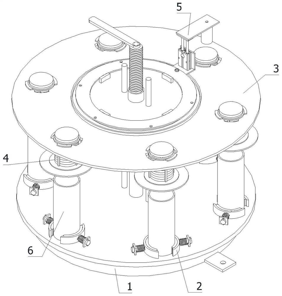
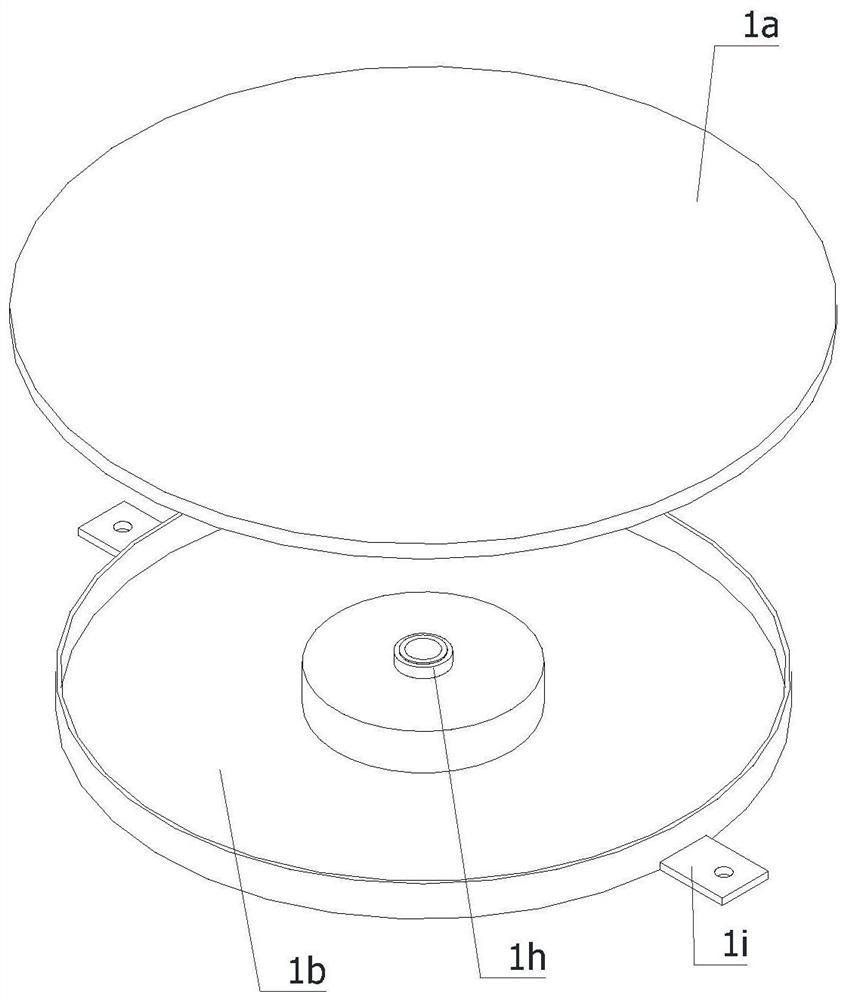
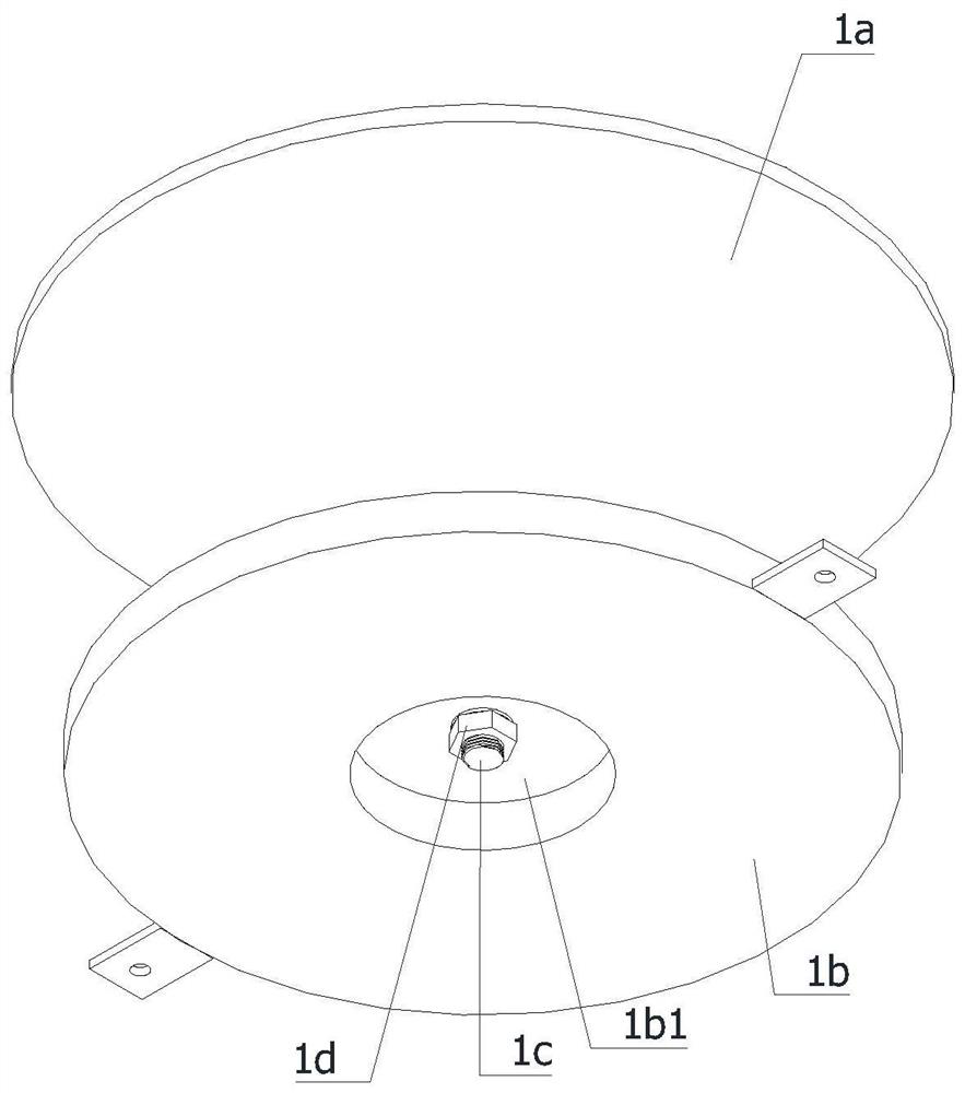
[0040] refer to Figure 1 to Figure 9 The shown equipment for testing the ultimate bearing capacity of a concrete-filled steel tube axially compressed short column includes a swivel seat 1, a height adjustment frame 3, a stamping mechanism 5, several clamping mechanisms 2 and a pressing mechanism 4, and the swivel seat 1 is fixedly installed in the working On the table, the height adjustment frame 3 is fixedly ins...


PUM


Abstract

The invention relates to the field of bearing capacity testing of concrete-filled steel tubes. The invention particularly relates to equipment and a method for testing ultimate bearing capacity of a concrete-filled steel tube axial compression short column. The equipment comprises a rotating base, a height adjusting frame, a stamping mechanism, a plurality of clamping mechanisms and a plurality of pressing mechanisms. The height adjusting frame is fixedly mounted at the top of the rotating base; the plurality of clamping mechanisms are fixedly mounted at the top of the rotating base; the plurality of pressing mechanisms are all mounted on the height adjusting frame. According to the equipment for testing ultimate bearing capacity of the concrete-filled steel tube axial compression short column, concrete-filled steel tubes with different diameters are clamped through the clamping mechanisms; a long-time ultimate bearing capacity test is carried out on the concrete-filled steel tubes through the pressing mechanisms; the stamping mechanism is used for testing the ultimate bearing capacity of transient strong stamping of the concrete-filled steel tubes, so that the concrete-filled steel tubes are not prone to shaking in the testing process, measurement data are prevented from being affected, the equipment is convenient to transport, and a construction site is always convenient totest.

Description

technical field [0001] The invention relates to the field of testing the bearing capacity of concrete-filled steel tube concrete, in particular to a device and a method for testing the ultimate bearing capacity of a concrete-filled steel tube concrete axially compressed short column. Background technique [0002] Concrete filled steel pipe is to pour concrete into the steel pipe and compact it to increase the strength and rigidity of the steel pipe. Generally, we call the concrete-filled steel tube concrete with a concrete strength level below C50 called ordinary steel-filled steel tube concrete; the concrete-filled steel tube with a concrete strength level above C50 called high-strength steel tube concrete; . When measuring the ultimate bearing capacity of conventional CFST, there is no special equipment to fix the CFST, which makes the CFST easy to shake during the long-term test process, which affects the measured data. Concrete filled steel tubes often need to be teste...

Claims


Application Information

Patent Timeline
Patent Type & Authority Applications(China)
IPC IPC(8): G01N3/12
CPCG01N3/12G01N2203/0003G01N2203/0019G01N2203/0044
Inventor 赖秀英郑娟
Owner PUTIAN UNIV
Learn More