Adaptive beamforming method for aviation communication
An adaptive beam, aeronautical communication technology, applied in the field of adaptive beam forming, can solve the problem of not using UE location information
- Summary
- Abstract
- Description
- Claims
- Application Information
AI Technical Summary
Problems solved by technology
Method used
Image

Examples
Embodiment 1
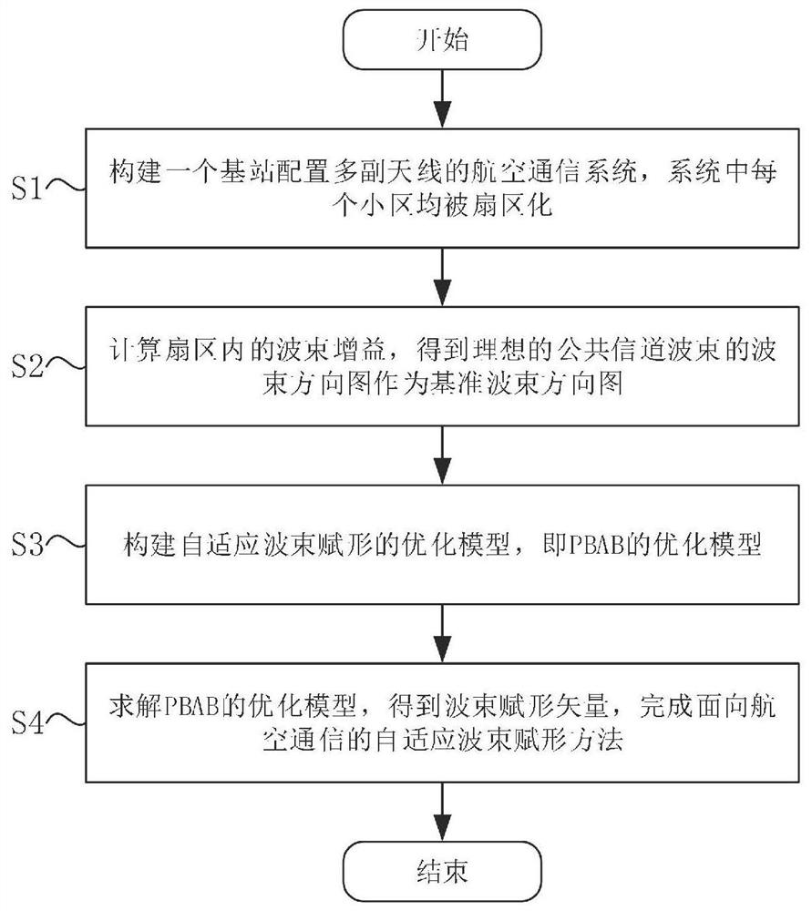
[0105] Such as figure 1 As shown, the adaptive beamforming method for aviation communication includes the following steps:
[0106] S1: Construct an aeronautical communication system with base stations equipped with multiple antennas, and each cell in the system is sectorized;
[0107] S2: Calculate the beam gain in the sector, and obtain the beam pattern of the ideal common channel beam as the reference beam pattern;
[0108] S3: Construct an optimization model of adaptive beamforming, that is, an optimization model of PBAB;
[0109] S4: Solve the optimization model of PBAB, obtain the beamforming vector, and complete the adaptive beamforming method for aviation communication.
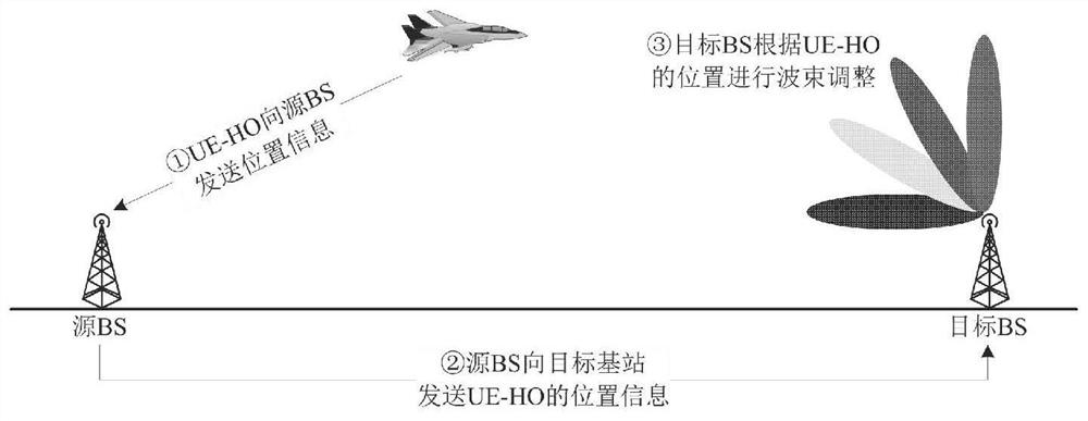
[0110] In the specific implementation process, the adaptive beamforming method for aeronautical communication provided by the present invention has the following advantages: since the serving cell switching usually occurs when the UE is at the edge of the cell, the PBAB scheme can provide the UE in ...
Embodiment 2
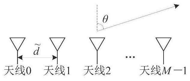
[0112] More specifically, on the basis of Embodiment 1, the present invention is specifically as follows: Consider an aeronautical communication system in which a BS is configured with multiple antennas, each cell is sectorized, and the angular interval of the sector is S=[θ min ,θ max ], θ min and θ max represent the minimum and maximum values of the sector angles, respectively. For example, for a 3-sector cell, For a 6-sector cell, In each sector, the BS uses a uniform linear array (Uniform Linear Array, ULA) with M antennas to serve UEs in the sector. Define the normalized antenna spacing as in is the actual antenna spacing, and λ is the carrier wavelength. figure 2 A schematic diagram of the ULA is drawn.
[0113] in the picture Indicates the angle of departure (Angle of Departure, AOD) of the signal. The steering vector of the ULA pointing to the θ direction is:
[0114] v(θ)=[1 e j2πdsinθ e j2π2dsinθ …e j2π(M-1)dsinθ ] T ∈C M (1)
[0115] Defi...
Embodiment 3
[0189] More specifically, in order to more fully illustrate the beneficial effects of the present invention, the effectiveness and advancement of the present invention will be further described below in conjunction with the simulation analysis and results of specific embodiments. We will select the actual number of BS antennas, the number of UE-HO and other parameters, calculate the beamforming vector according to Algorithm 2, and evaluate the performance of the PBAB scheme proposed by the present invention through simulation. The main simulation parameters are given in Table 1.
[0190] Table 1 Simulation parameter table
[0191] Number of BS antennas, M 64 Normalized antenna spacing, d 0.5 Gain adjustment factor, η 0.95 The discretization number of θ, Q 256
[0192] A. Beam pattern
[0193] First, we will demonstrate the applicability of the PBAB scheme proposed in this patent to sectors of different sizes. We consider three sector ranges,...
PUM
 Abstract
Description
Claims
Application Information
 - R&D
- Intellectual Property
- Life Sciences
- Materials
- Tech Scout
- Unparalleled Data Quality
- Higher Quality Content
- 60% Fewer Hallucinations
Browse by: Latest US Patents, China's latest patents, Technical Efficacy Thesaurus, Application Domain, Technology Topic, Popular Technical Reports.
© 2025 PatSnap. All rights reserved.Legal|Privacy policy|Modern Slavery Act Transparency Statement|Sitemap|About US| Contact US: help@patsnap.com