Cover glass, and in-cell liquid-crystal display device

A technology of cover glass and strengthened glass, which is applied in the direction of glass/slag layered products, chemical instruments and methods, coatings, etc., can solve the problems of white turbidity of liquid crystal screen and electrification of liquid crystal elements, so as to prevent white turbidity and inhibit Effect of triboelectric charging and high mobility

Active Publication Date: 2020-09-29
ASAHI GLASS CO LTD
View PDF16 Cites 0 Cited by
  • Summary
  • Abstract
  • Description
  • Claims
  • Application Information

AI Technical Summary

Problems solved by technology

[0007] On the other hand, in-cell liquid crystal display devices (especially IPS liquid crystal display devices) have the problem that part of the liquid crystal screen becomes cloudy when touched by fingers.
This is because the touch panel, which is closer to the operator's side than the liquid crystal element, helps to eliminate static electricity in the plug-in type and on-cell type. There is no touch panel, so the liquid crystal element is easily charged by static electricity

Method used


Image

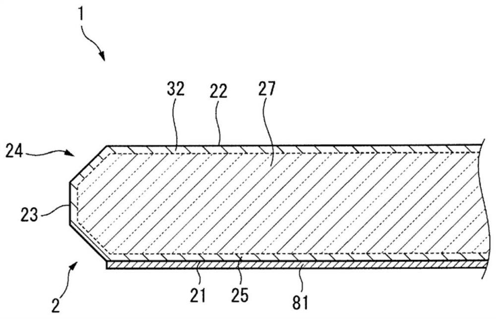
  • Cover glass, and in-cell liquid-crystal display device
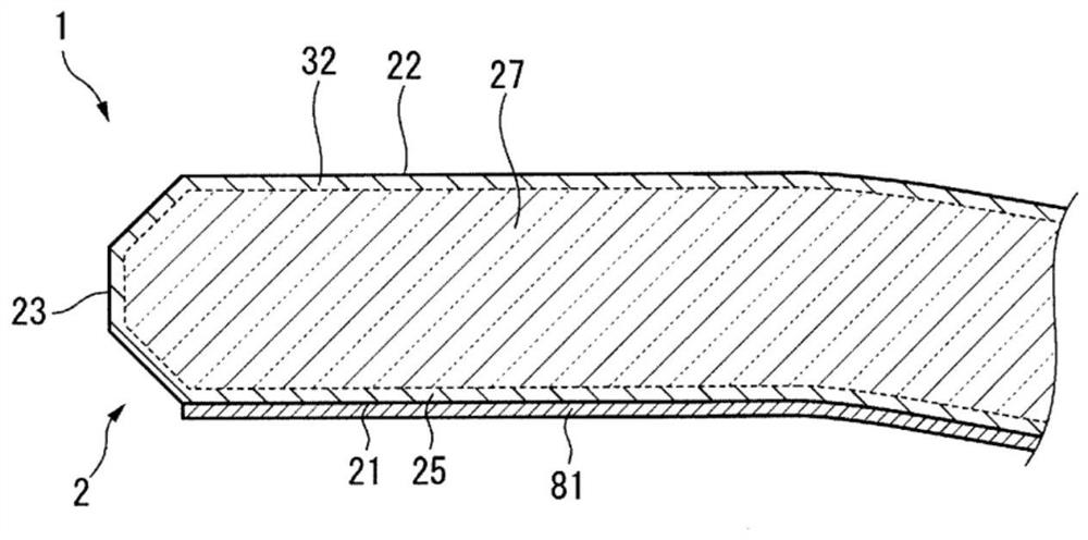
  • Cover glass, and in-cell liquid-crystal display device
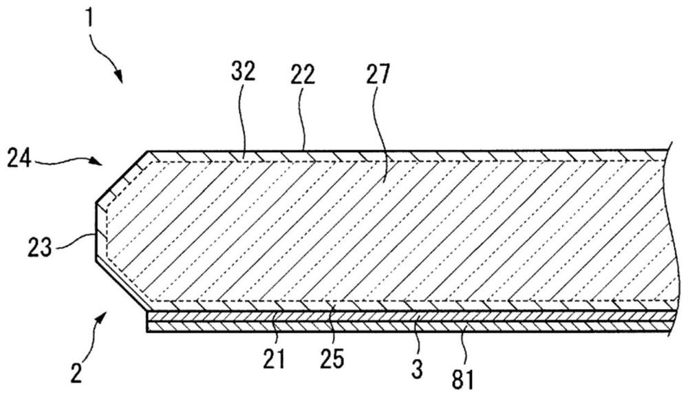
  • Cover glass, and in-cell liquid-crystal display device

Examples


Embodiment

[0227] Next, examples of the present invention will be described. The present invention is not limited to the following examples.

[0228] Cover glasses with various characteristics were produced, and the amount of charge and the degree of clouding when incorporated into the device were determined. The specific order is as follows. Examples 1 to 3 are examples, and examples 4 to 5 are comparative examples.

example 1

[0230] First, as glass before chemical strengthening, glass having a composition shown in Example 1 in Table 1 was produced by a float process to obtain a 0.7 mm glass plate. The obtained glass is cut into length 100mm and width 120mm respectively (the area of ​​the 1st principal surface is 12000mm 2 ), length 100mm and width 180mm (the area of ​​the first main surface 21 is 18000mm 2 ), 100mm long and 260mm wide (the area of ​​the first main surface 21 is 26000mm 2 ).

[0231] Next, these glasses are chemically strengthened. The conditions of chemical strengthening performed chemical strengthening by immersing in 100 weight% potassium nitrate molten salt of temperature 420 degreeC for 8 hours.

[0232] After cleaning the strengthened glass, a solution obtained by diluting Afluid S-550 manufactured by Asahi Glass Co., Ltd. with fluorine solvent ASAHIKLIN AC6000 manufactured by Asahi Glass Co., Ltd. to 0.1% by mass was applied to one surface by spraying to form an anti-finge...

example 2

[0250] As the glass before chemical strengthening, the raw material was prepared so that it might become the glass of the composition shown in Example 2 in Table 1, it melt|dissolved, and after flowing out into about 300 mm square block, it cooled slowly and obtained the glass body. Thereafter, cutting and cutting were performed to form a plate shape of 100 mm in length, 120 mm in width, and 0.7 mm in thickness; 100 mm in length, 180 mm in width, and 0.7 mm in thickness; 100 mm in length, 260 mm in width, and 0.7 mm in thickness.

[0251] Next, these glasses are chemically strengthened. The conditions of chemical strengthening performed chemical strengthening by immersing in 100 weight% potassium nitrate molten salt of temperature 450 degreeC for 3 hours after immersing in 100 weight% of sodium nitrate molten salt of temperature 450 degreeC for 3 hours.

[0252] Thereafter, the cover glass of Example 2 was produced under the same conditions as in Example 1.


PUM

PropertyMeasurementUnit
areaaaaaaaaaaa
depthaaaaaaaaaa
areaaaaaaaaaaa

Abstract

The purpose of the present invention is to provide a cover glass capable of preventing clouding without increasing the thickness of the display device or the number of production steps, and an in-cellliquid-crystal display device. The present invention relates to a cover glass equipped with a chemically strengthened glass having a first main surface and a second main surface with an area of 12000mm2 or greater and an anti-fingerprint treated layer provided on the first main surface in which the DOL of the chemically strengthened glass is 20 [mu]m or higher, the content of P2O5 in the tensilestress layer is 2 mol% or less, A*B is 135 or higher, and the triboelectric charge of the anti-fingerprint treated layer surface is from 0 kV to -1.5 kV.

Description

technical field [0001] The invention relates to a glass cover sheet and an embedded liquid crystal display device. Background technique [0002] There are cases where a touch function is mounted on an electronic device including a liquid crystal display device such as a car navigation system for an in-vehicle. The touch function referred to here refers to a function of inputting information by an operator touching or approaching the surface (cover glass) of the display device with a finger. [0003] As a configuration for realizing a touch function, there is an out-cell type in which a touch panel is mounted on a liquid crystal display device. [0004] In the plug-in type, even if one of the liquid crystal display device and the touch panel is defective, the other can be used, so the yield is excellent, but there are problems of increased thickness and weight. [0005] Therefore, an on-cell type liquid crystal display device in which a touch panel is sandwiched between a l...

Claims


Application Information

Patent Timeline
Patent Type & Authority Applications(China)
IPC IPC(8): C03C17/30B32B7/025B32B17/06C03C3/083C03C3/085C03C3/087C03C3/091C03C3/097C03C15/00C03C17/34C03C17/42C03C21/00G02F1/1333
CPCB32B7/025B32B17/06C03C3/085C03C3/087C03C3/091C03C17/34C03C17/42G02F1/1333C03C21/002C03C17/32C03C17/30C03C17/3668C03C17/3657C03C21/00C03C2217/73C03C2217/76C03C3/097C03C4/18C03C2204/00C03C2217/734C03C2217/75C03C2218/112C03C2218/151
Inventor 竹田洋介小池章夫池田徹斋藤康成府川真村上贵章
Owner ASAHI GLASS CO LTD
Why Eureka
Try Eureka