A standing resistance hip extension training device

A training device and standing position technology, applied in the field of training devices, can solve problems such as troublesome operation, and achieve the effect of convenient operation

Active Publication Date: 2021-08-06
济宁景泽信息科技有限公司
View PDF8 Cites 0 Cited by
  • Summary
  • Abstract
  • Description
  • Claims
  • Application Information

AI Technical Summary

Problems solved by technology

[0004] In order to overcome the need to tie the elastic rope to a fixed object, and then carry out resistance hip extension training, the operation is cumbersome, and the elastic rope needs to be re-tied for each training, which is relatively laborious. The purpose of the present invention is to provide a It is more convenient for patients to perform standing resistance hip extension training without re-tying the elastic rope, which is a relatively labor-saving standing resistance hip extension training device

Method used


Image

  • A standing resistance hip extension training device
  • A standing resistance hip extension training device
  • A standing resistance hip extension training device

Examples


Embodiment 1

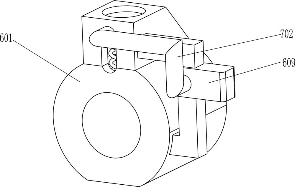
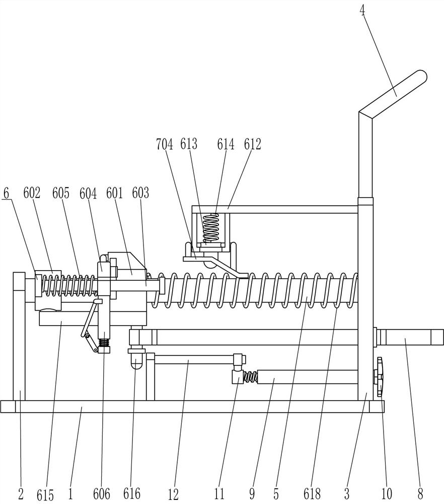
[0023] see Figure 1-Figure 5 , a standing resistance hip extension training device, including a base plate 1, a support plate 2, a mounting plate 3, an armrest 4, a first guide rod 5, a rope release assembly 6, a rope collection assembly 7, an elastic pull cord 8 and a limiter Bit block 801, the support plate 2 is fixedly connected to the front and rear sides on the left side of the top of the bottom plate 1, the mounting plate 3 is fixed to the front and rear sides of the top right side of the bottom plate 1, and the handrail 4 is fixed to the top of the mounting plate 3 on the front and rear sides A first guide rod 5 is fixedly connected between the upper left side of the front mounting plate 3 and the upper right side of the front support plate 2, the upper left side of the rear mounting plate 3 and the upper right side of the rear support plate 2 The first guide rod 5 is also fixedly connected between them, and a rope release assembly 6 is provided between the first guide...

Embodiment 2

[0030] see figure 1 and figure 2 The main difference between this embodiment and embodiment 1 is that this embodiment also includes an internal threaded pipe 9, a knob 10, a screw 11, a second guide rod 12 and a third slider 13, and the top left side of the bottom plate 1 Two second guide rods 12 are fixedly connected to the front and rear parts, and a third slider 13 is slidably arranged between the two second guide rods 12 on the front side and the two second guide rods 12 on the rear side. The third slider 13 cooperates with the movable rod 616, the middle of the bottom of the third slider 13 is fixedly connected with the screw rod 11, and the middle of the lower part of the mounting plate 3 is rotationally connected with an internally threaded pipe 9, and the internally threaded pipe 9 is located below the elastic pull cord 8 , the screw rod 11 is located in the internally threaded pipe 9 to cooperate with it, and the right end of the internally threaded pipe 9 is fixedl...

Embodiment 3

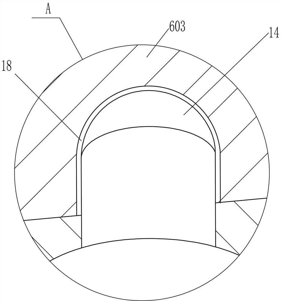
[0033] see image 3 , Figure 5 and Figure 6 Compared with Embodiment 1 and Embodiment 2, the main difference of this embodiment is that in this embodiment, it also includes the second clamping lever 14, the seventh spring 15, the rotating plate 16 and the connecting rod 17, and the bottom of the rectangular rod 603 is opened in the middle. There is a second clamping slot 18, and the hollow pull rod 606 is slidingly provided with a second clamping rod 14, the top of the second clamping rod 14 is located in the second clamping groove 18 to cooperate with it, and the inner bottom of the second clamping rod 14 is connected to the bottom of the hollow rod 606 The seventh spring 15 is wound around, the second clamping rod 14 is hinged with a connecting rod 17 at the lower left side, and the upper left side of the hollow pull rod 606 is hinged with a rotating plate 16, and the lower part of the right side of the rotating plate 16 is connected with the connecting rod 17 at the end....


PUM


Abstract

The invention relates to a training device, in particular to a standing resistance hip extension training device. The technical problem is how to design a kind of standing resistance hip extension training device that can make patients more convenient to perform standing resistance hip extension training without re-tying the elastic rope, which is relatively labor-saving. A hip extension training device for standing resistance, comprising: a base plate, a support plate is symmetrically fixed to one side edge of the base plate; a mounting plate, and the mounting plate is symmetrically fixed to the One side of the bottom plate corresponds to the support plate. In the present invention, by pulling the hollow pull rod to move to the right, the clamp block cooperates with the first slot to fix the first guide sleeve, and the elastic pull cord shrinks and resets. Pull rope stretching for standing resistance hip extension training, so that the operation is more convenient and labor-saving.

Description

technical field [0001] The invention relates to a training device, in particular to a standing resistance hip extension training device. Background technique [0002] Knee joint: The knee joint is composed of the lower end of the femur, the upper end of the tibia, and the patella. It is the largest and most complicated joint in the human body. After joint surgery, most patients will experience quadriceps atrophy, and strength training is required to shorten the recovery time. [0003] At present, standing resistance hip extension training is one of the methods. First, the patient needs to tie one end of the elastic rope to a fixed object, then put the other end of the elastic rope on the calf, and then continuously pull the elastic with the calf. It is cumbersome to perform resistance hip extension training with rope and pull rope, and every time you train, you need to re-tie the elastic rope, which is laborious and affects the training efficiency. Contents of the inventi...

Claims


Application Information

Patent Timeline
Patent Type & Authority Patents(China)
IPC IPC(8): A63B23/04A63B21/055
CPCA63B21/0552A63B23/0488
Inventor 张娟文丽孙化娟覃灿凤
Owner 济宁景泽信息科技有限公司
Why Eureka
Try Eureka